SmartDrive Protect Installation Best Practices
Overview
The following installation instructions define steps that improve the quality of the install and operation of the SmartDrive Protect device.
Note: When replacing a windshield/windscreen, use the Windshield/Windscreen Replacement Guide.
Camera Installation Instructions
Mounting Location
Mount the camera on the windshield as high as possible.
Mount the camera off-center towards the driver.
The camera lens must not be located behind the dot matrix.
Make sure it will not block airbag deployment.
The camera cannot interfere with a driver’s line of sight to the road, traffic signals, or road signs.
Adhere to your country, state, and/or municipality’s mounting laws.
Details
Before removing the adhesive backing, check to make sure the camera fits properly.
- Using an alcohol pad clean the windshield and wipe dry with a lint-free clean cloth.
- Press firmly on camera bracket for 10 seconds to ensure adhesion.
- Use a self-adhesive cable clip to secure the cable to the windshield.
- Route the cable around the top of the windshield and down the A-pillar to the fuse box. Ensure it does not obstruct the driver's view.
- Ensure the cable doesn’t get pinched. Create an 8 inch loop of the excess cable and secure under the dashboard.
Acceptable Camera Views
Road-facing Camera
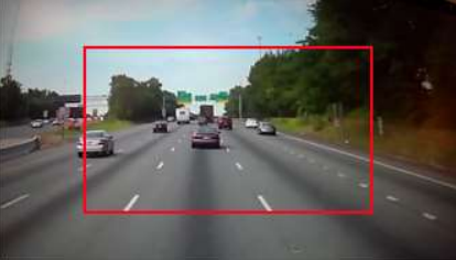
Check the live preview on the companion app for both cameras (road and driver) and ensure they are oriented as mandated in the mounting guidelines.
The Horizon line (in red) to be in the range denoted by the green band, to ensure the camera sees enough of the road and not looking mostly at the sky.
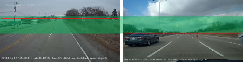
Good Mounting in a truck Good mounting in a car
Cab-facing Camera
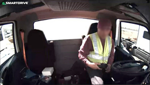
The camera should see as much of the driver as possible which includes:
- The driver's face and torso as shown above
- Driver's hand on the steering wheel
- When possible the seat belt.
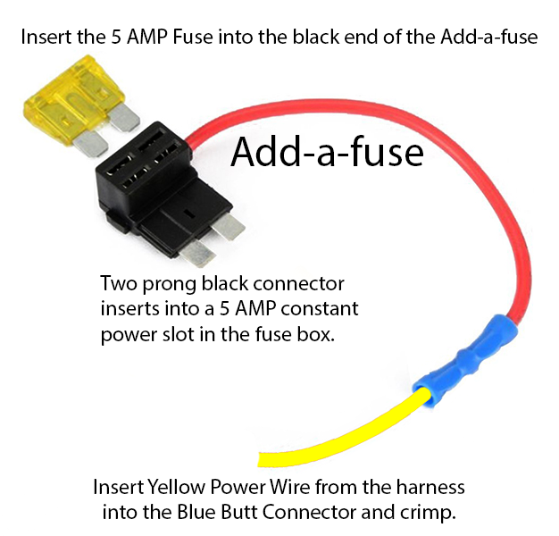
Constant 12 volt power wire (yellow wire on the wiring harness)
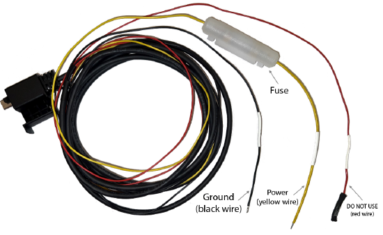
- Connect the Add-a-fuse to the yellow wire on the wiring harness.
- Find the Fuse box
- Identify a 12 volt Constant Power source
- A Digital Multi-meter is used to confirm uninterrupted constant power
Details
Test connection with a Digital Multimeter to verify source is 12 volt switched ignition
How to locate Constant Uninterrupted Power with a Digital Multimeter:
Test for constant 12vDC (in all key positions)
With the ignition ON (running), Ignition OFF and while cranking.
Verify constant battery voltage remains constant and does not drop below 10vDC
- Insert the black two-pronged end into the 12 volt power port in the fuse box.
Chassis Ground wire (black)
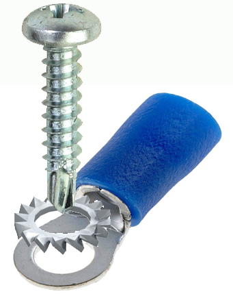
- Use a #10 ring terminal. Attach the ring terminal to the end of the black wire on the wiring harness.
- Scrape surface near the vehicles fuse box and use ¼ inch self-tapping screw to connect the ground wire to the chassis.
- A Digital Multimeter is used to confirm Chassis Ground.