Workflow 2.0 Engineering Documentation
Table of Contents
1) Introduction
2) Definitions and Terms
3) Workflow Folder Structure
4) DriverWorkflowApplication
a) TripManagerApplication class
b) Messenger class
c) Migration folder
d) TaskFactory folder
e) Template folder
5) DriverWorkflowWinformsUI
a) TripManagerAppUI class
b) Workflow views
c) Workflow TaskForms
d) Resources folder
6) WorkflowApplicationToolkit
a) Validation folder
b) IO folder
c) Object Definitions
7) WorkflowSerialization
8) Build Environment
9) Building the Workflow Solution
10) Remotely Connecting to the Unit
11) Deploying Workflow to the Unit
12) Debugging
13) Sending TripPlans to MCP50/IVG
14) Workflow Return Messages
15) Simulating Data
16) Basic Template Features
17) Unit NVRAM Reset
18) AppTest
19) Common Tips and Tricks
20) Other Workflow Resources
Introduction
This is a brief guide for building, deploying and using Workflow standard truck load (TL) template.
Definitions and Terms
TL - truck load
TM - trip manager
UA - Unit Address, this is the unique 9-digit identifier for each unit
Trip Plan - The list of destinations for the active trip; there is only a single trip plan on the unit. Sending a new trip plan (even if it's an exact copy of the old trip plan) deletes the previous trip plan.
PrePlan - This is a type of trip plan for a non-active trip; there can be multiple PrePlans on the unit.
Destinations - A specific "stop" within the trip plan
Task - Workflow tasks, each trip plan consists of destinations and each destination has several tasks
TaskForm - A form for a specific type of task
TaskFactory folder - See section 4, "DriverWorkflowApplication".
Migration folder - See section 4.
Resources folder - See section 4.
Data, datums - The TripPlans, add new task messages, delete task message, etc. are sent to the unit in an xml format organized by outer <data> tags and inner <datum> tags.
Protocol Buffers - Aka "protobuf"; for more information, see here: https://developers.google.com/protocol-buffers/?hl=en![]() .
.
SecureCRT - This is a terminal emulator client that is used to display active running logs and other information about the units; for more information, see here: https://www.vandyke.com/products/securecrt/![]() . Note: Omnitracs employees should contact Omnitracs-IT to receive this program. PuTTY can also be used, as an alternative (PuTTY download: http://www.chiark.greenend.org.uk/~sgtatham/putty/download.html
. Note: Omnitracs employees should contact Omnitracs-IT to receive this program. PuTTY can also be used, as an alternative (PuTTY download: http://www.chiark.greenend.org.uk/~sgtatham/putty/download.html![]() ).
).
Workflow Folder Structure
The screenshot below shows the four main Projects in the Workflow Solution. The suffix "-TL" denotes this particular example is for the TL template, but all other templates should have the same core functionality.

• The DriverWorkflowApplication project contains the domain logic. Of particular note are TripManagerApplication class, Messenger class, the classes within the Migration folder, & the classes within the TaskFactory folder. Configuration data specific to the template is contained in the folder labeled after the template name ("TL", "TM", etc.).
• The DriverWorkflowWinformsUI project contains UI elements. Of particular note are the TripManagerAppUI class, the Workflow views, the Workflow TaskForms, and the Resources folder. All of the UI handling is done within this project.
• The WorkflowApplicationToolkit project works in conjunction with Workflow Engine (the engine resides in the eTIU or oTIU solutions for MCP50 and IVG, respectively) and handles validation and IO. TaskForm elements, Field elements, and XML handling are all defined within this project.
• The WorkflowSerialization project handles serialization and deserialization of the TripPlans. Serialization/deserialization is done using the protocol buffers method of serialization. This project also interacts heavily with the Workflow Engine.
DriverWorkflowApplication
This project contains the domain logic for the Workflow app. The screenshot below shows the folder and file structure of this project.
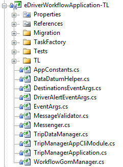
• The TripManagerApplication class drives a lot of the behavior of the Workflow solution. In a way, all of the basic functionality of Workflow is handled by this class. TripPlans, PrePlans, Tasks, and Destinations are all added, updated, or deleted using methods within this class.
• The Messenger class sends/receives messages, such as "Task Added" or "New TripPlan received". This class also converts XML data/datums to the Workflow object model. Data is coming from host to mobile in the form of forward messages and sent back to host in the form of return messages. Both forward and return messages are handled in Messenger class.
• The Migration folder contains the classes that handle migration of data to/from a small database, local to the MCP. Data interfaces define how this information is structured. The MigrationLoader loads global history records.
• The TaskFactory folder contains the classes that are responsible for creating Workflow tasks. The type of task is defined at the time of the task creation call. Task validation rules are assigned to specific forms in the TaskValidationHelper.cs file.
• The TL folder (name of the template) contains configuration data specific to the template. The manifest defines the Workflow version and the template type for the MCP50/IVG version button, which is found on the unit clicking the "System" dashboard button, then clicking on the System tab, and then hitting the Version button in the lower right corner.
DrivewWorkflowWinformsUI
This project contains all the UI logic for the Workflow app. The screenshot below shows the folder and file structure of this project.
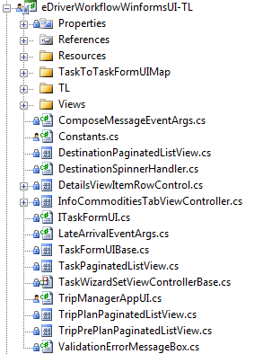
• The TripManagerAppUI class functions like the AppUI classes in the TIU, eTIU, & oTIU solutions. This means that it contains metadata such as application name, title, dashboard icon, and alert string. This class is underpinning for the rest of the Workflow UI.
• The Views folder contains the Workflow views. As an example, "Auto Arrival Detected" is a view. Any logic specific to Auto Arrival is contained within the AutoArrivalDetectedView, such as which view is displayed when the "confirm" button is clicked. In terms of basic functionality, these views function exactly as the views within the TIU, eTIU, and oTIU solutions do.
• The TaskForms folder (Views/TaskForms) contains the Workflow task forms. These task forms are generally accessed via the Tasks tab when the user has selected a destination, although some task forms can also be accessed via the Send Message tab. (Note: The Send Message tab can be found by opening Workflow on the unit, then
• The Resources folder contains all icons associated with Workflow UI. These icons are assigned programmatically in the view or form that needs them.
WorkflowApplicationToolkit
This project works in conjunction with Workflow Engine. The screenshot below shows the folder and file structure of this project.

• The Validation folder validates task fields based on the assigned validation rules. As mentioned above, Validation rules are assigned in the "../DriverWorkflowApplication/TaskFactory/ TaskValidationHelper.cs" file.
• The IO folder aids in data input/output. It contains classes for a data input stream and a data output stream, as well as a StringWriter class.
• The basic attributes of a TaskForm, Fields, and XML are defined in their respective folders.
WorkflowSerialization
This project also works in conjunction with the Workflow Engine, but with the express purpose of serializing and deserializing TripPlans. The screenshot below shows the folder and file structure of this project.

• The WorkflowSerializer class uses the WorkflowProtoSerializer (object defined/created in the TIU, eTIU, or oTIU solution) to serialize and deserialize trip plans. This is done through use of the protobuf-net.dll file.
Build Environment
The build environment varies depending upon which type of unit Workflow 2.0 will be deployed to. Below are the requirements for the two differing solutions.
The MCP50 version of the Workflow 2.0 solution uses the following:
• Visual Studio 2008 Professional, with Service Pack 1;
• and Microsoft .NET Framework 3.5.
• Platform verification also must be skipped. In order to disable platform verification, follow the below steps:
1. Go to the following directory: C:\WINDOWS\Microsoft.NET\Framework\v3.5\.
2. Find Microsoft.CompactFramework.Common.targets file, create a copy, and open the original file in a text editor.
3. Find the below statement (use ctrl+F) in the file:
<Target Name="PlatformVerificationTask"> <PlatformVerificationTask PlatformFamilyName="$(PlatformFamilyName)" PlatformID="$(PlatformID)" SourceAssembly="@(IntermediateAssembly)" ReferencePath="@(ReferencePath)" TreatWarningsAsErrors="$(TreatWarningsAsErrors)" PlatformVersion="$(TargetFrameworkVersion)"/> </Target> .
4. Edit the statement, such that the highlighted statement is added:
<Target Name="PlatformVerificationTask" Condition="'$(SkipPlatformVerification)' == 'true'"> <PlatformVerificationTask PlatformFamilyName="$(PlatformFamilyName)" PlatformID="$(PlatformID)" SourceAssembly="@(IntermediateAssembly)" ReferencePath="@(ReferencePath)" TreatWarningsAsErrors="$(TreatWarningsAsErrors)" PlatformVersion="$(TargetFrameworkVersion)"/> </Target> .
5. Save the file and close the text editor.
• Finally, the following two environment variables must be added. Instructions on how to add an environment variable are here: https://kb.wisc.edu/cae/page.php?id=24500![]() .
.
o BuildType=WINCE_6
o TargetFrameworkVersion=v3.5
The IVG version of the Workflow 2.0 solution uses the following:
• Microsoft Visual Studio 2013, Update 4;
• Microsoft .NET Framework 4.5;
• Application Builder for Windows Embedded Compact 2013;
• and the Omnitracs_OTIS_SDK.msi (found here: \\princeville\mobilbuilds\OTIS1.0\OS_Releases\SDK\1.0.0.16).
Building the Workflow Solution
Building the Workflow solution and putting it on the device is rather simple. The steps are detailed below.
1. We need to build the eTIU (MCP50) or oTIU (IVG) solution before building the workflow solution. Details on how to this (and what is required) are contained in the Omni-Wiki. See the following pages: MCP50 Startup Guide or OTIS_Quick_Start document.
2. Once the eTIU, or oTIU solution is built, make sure that you are about to build the Workflow solution as a Release build for any CPU. For MPC50, ensure the target device is "Pocket PC 2003 SE Emulator".
3. Build the Workflow solution. This will create a package file named "workflow.pkg" (MCP50) or "driverworkflow.pkg" (IVG) in the following directory:
..\mobile\apps\mcp50\latest\SW\Workflow\Apps\Common\WinFormsUI\bin\eRelease.
Remotely Connecting to Units
Sometimes, it is useful to remotely connect to the unit, either to access the Workflow folder & file structure on the unit. One of the prime examples of this is putting Workflow on a unit. Here are a few ways to remotely connect to the MCP50/IVG units.
• Remotely connecting with FTP:
1. Download the FileZilla FTP program, which is free and can be found at https://filezilla-project.org/![]() .
.
2. Enter the IP address of the unit in the "Host" textbox.
Note: On the MCP50/IVG devices, no username or password is required. Leave the Port textbox empty, as well.
3. Click "Quick Connect". Wait until the Status panel shows "Status: Connected".
4. Once connected, the left side panel, named "Local site", shows the directory of your Windows PC. The right side panel, name "Remote site", shows the directory of the MCP50/IVG unit.

5. Files can now be transferred by either copying them from directories in the Local site to the Remote site or by dragging files into the Remote site.
• Remotely connecting with ActiveSync Remote Display:
1. Copy the files from the following directory onto your Windows PC: ..\mobile\apps\mcp50\latest\Tools\MCP50RemoteDesktop.
2. Install WindowsMobilePowerToys.msi onto your Windows PC.
3. Run the program "ActiveSync Remote Display" on your Windows PC.
4. Copy cerdisp2.exe to the following directory on the unit with which you are remotely connecting: ../Windows.
5. On the unit, rune cerdisp2.exe inside the Windows folder.
6. Enter the IP address of your Windows PC and click "Ok".
7. You are now remotely connected to the unit. You can click on the remote connection window and control the device. For example, clicking the home button inside this window will have the same effect as clicking the home button on the unit itself. Files cannot be moved via this method of remotely connecting.

Deploying Workflow to Units
When you have built the Workflow solution is Visual Studio (required) and have remotely connected to the unit (optional), the Workflow package needs to be deployed to a unit.
1. Once you have .the package file, there are a few ways to get the Workflow template files on the unit itself.
a. The package can be unzipped using a common package unzipping program like 7zip or WinRAR. Then, the files can be moved to the device using either a USB stick or using FTP (see above for FTP). The following directory on MCP/IVG is the Workflow template directory: ..\IFlash\AppData\Workflow\Current.
Note that the device must be restarted after doing it manually in this way.
b. The service portal can be used. Once logged on, select the "Workflow Management Center" button. Then, choose an already created Workflow version or click "Create New Workflow". After selecting/creating your Workflow version, deploy to mobile and select the UA(s).
If deploying to multiple devices, it is recommended that the Service Portal is used.
2. Once the Workflow package is on the unit (and the unit has been restarted if needed), ensure that the Workflow button on dashboard is selectable and that the MCP50/IVG version button shows the correct version.
a. If the Workflow dashboard button is NOT selectable, ensure that:
i. A driver is logged in on the unit.
ii. Workflow is enabled in Mongoose/Service Portal.
b. If the Workflow version is not correct, ensure you have the latest version of Workflow.
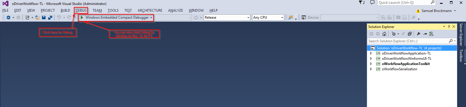
Debugging
On the MCP50, live debugging in Visual Studio is not possible, due to hardware constraints. However, on IVG, live debugging can be done. Simply click on the Debug menu to begin doing so. Live debugging allows errors/exceptions to be shown inside the error window in Visual Studio itself.
On both types of units, it is possible to see actively running logs. To do so, you will need SecureCRT, a serial-to-usb cable, and a powered USB hub. Below are the steps on how to see actively running logs.
1. Ensure that you have the correct serial-to-usb cable setup.
a. For MCP50, the correct serial-to-usb cable setup consists of a serial-to-usb cable (serial end is male), a Null Modem adaptor, and another serial-to-usb cable (serial end is also male). Without the Null Modem adaptor, the logs will NOT show. Simply connect one end of the setup the usb hub connected to the USB and the other end of the setup to your Windows PC.

b. For IVG, the correct serial-to-usb cable setup consists of a serial-to-usb cable with the serial end connected to the App Debug Port of the IVG unit and the usb end connected to your Windows PC.

2. Find out which com port the serial-to-usb cable setup is connected to by opening Device Manager on your Windows PC and selecting "Ports (COM & LPT)". In parentheses, next to "USB Serial Port", it will list which com port that serial-to-usb cable is connected to. For example, it will say "USB Serial Port (COM9)" if the setup is connected to com port 9.
3. In SecureCRT, right click on "Sessions" and select "Quick Connect".
4. In the Quick Connect window, change the protocol to "Serial", change the port to the com port which the serial-to-usb cable is connected to, and change the baud rate to 115200. Now, click the "Connect" button.
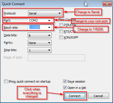
5. Actively running logs should now start showing in the SecureCRT main window.
a. If logs are not showing, try restarting the unit.
b. If the logs are not showing after unit restart, then you do not have the correct serial-to-usb cable setup.
Note: There only needs to be one saved logging session for both MCP50 & IVG. Any additional logging sessions are optional.
6. Right click on the saved logging session and select "Properties". Now, select "Log File".
a. Create a name and set the directory for the log file by clicking on the "..." button underneath "Log file name".
b. Ensure "Overwrite file" is checked, otherwise the file will append every time you start logging.
c. Also ensure that "Start log upon connect" is checked.
d. Click "OK".

7. On the unit, click on the Diagnostics dashboard button. Enter the UA as the password. The UA is found in the Systems app, on the Systems tab.
8. In Diagnostics, click on the "Settings" button.
9. The trace level for Workflow can be changed to debug, in this window, by finding the Workflow key and choosing "Debug" as the value. The "Workflow" and "WorkflowLocationService" keys will probably need to be set to debug.
10. Ensure the "Quick Trace" checkbox is selected and click "Set. Click "Done" or "Home" after you have set both keys.
11. Workflow debug statements will now appear in the SecureCRT window.
12. (Optional) In order to make Workflow statements pop out from the rest of the logs, it might be useful to do the following:
a. Right click on the (saved) logging session in SecureCRT and click on "Properties".
b. Click on "Appearance". Under "Highlight keywords", click on "Edit".
c. Enter the following words and click add after entering each word: workflowlocationservice, workflow, driverworkflow, & driverworkflowui.
d. Select each of these words and click "Set Color..." to choose a color for this term.
e. Click "Ok" and then "Ok" again.
f. Restart the Log Session. The words that were previously highlighted will now be shown in SecureCRT in whatever color was chosen.
Difference between a Forward Msg & Return Msg
There are two types of Workflow messages that unit will be aware of: forward messages and return messages. Forward messages are messages that the unit receives from WSClient or the Service Portal. An example of a forward message is a trip plan message, sent via the service portal. Return messages are messages that unit sends back. An example of a return message is the message that unit sends back after the unit arrives to a destination.
Sending TripPlans to MCP50/IVG
Workflow requires a trip plan or preplan to use most of its functionality. Detailed below is how to send a Trip Plan. Note that PrePlans are also sent in the same way, as are changes to tasks, new tasks. Trip Plans, PrePlans, and tasks can also be removed in the same way. Basically, XML messages are sent to the unit and interpreted by Workflow. There are a few different way to do this.
• Using WSClient:

1. Download WSClientApp from the following location: //TBD
2. Find the files "WSClientApp1.1.exe.config" and "WSClientApp1.1.vshost.exe.config". These configuration files will need to be changed.
a. Change the account number. This is your customer account number. For example, mobile dev has an assigned customer account number. Ideally, this account number is the same account number as the account number the unit is assigned to.
b. Change the username to your username.
c. Change the UA to the unit address of your device.
3. Run WSClientApp1.1.exe.
4. Click on the "ForwardMsg" button.
5. Copy the trip plan xml details in the textbox within the "Payload" window.
a. Optional: You can also choose to save this trip plan as an xml file on your local machine. Do note that, if you choose to do so, you will need to scroll down in the "Template" scroll box to reselect your trip plan.
6. Click the "Send Message" button or the "Save and Send Msg" button.
7. After a few seconds, WSClient should display the following popup dialogue:
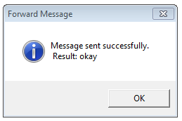
8. Click "OK". The trip plan will now be sent OTA.
9. When the unit receives the trip plan, the below popup dialogue will be shown on the unit:

The unit logs will also show a block of XML text for this new Trip Plan, and the History tab will show an entry for it.
a. Similar popup dialogues will be shown for PrePlans and tasks. If Trip Plans, PrePlans, and tasks are removed, it will also show a popup dialogue.
10. Click "View" to see the Trip Plan displayed within the Workflow app.
• Using CLI:
1. Either use the unit's CLI dashboard app (enabled via Mongoose) or use telnet to connect to the device.
2. Put eMashT.exe on the device. This program can be found at the following location: //TBD
3. Use the command "CD IFlash" and then the command "eMashT". eMashT will now start.
4. Type the command "load_module WorkflowLoaderApplication.WorkflowLoaderAppCliModule WorkflowLoaderApplication.dll" and then the command "load_module TripManagerApplication.TripManagerAppCliModule TripManagerApplication.dll".
5. Rename the TripPlan file "TestTripPlan.xml" and put this file in the following directory on the unit: ../IFlash/AppData/Workflow.
6. Type the command "tm_add_new_trip_plan_from_file".
7. The new TripPlan popup should now be displayed. (See step #9 above.)
Workflow Return Messages
The unit will send Return Messages from Workflow OTA. These can be viewed via WSClient. Ensure that WSClient is installed and running (see "Using WSClient" section above). The process of viewing Return Messages is detailed below:

1. Click on the "GetMessage" button.
2. Make sure the "ESS" option is selected.
3. Click the "Get Messages" button.
4. The recent return messages will be shown in the textbox under "Response". These will have the same type of XML format as Forward Messages.
a. If there are no recent return messages, the textbox will show "ESS Queue is empty".
b. A return message is only shown in the ESS Queue for a few minutes.
Basic Template Features
There are several Workflow template features that users should familiarize themselves with. Below are Screenshots and descriptions of these features.
• Trip Plan View:
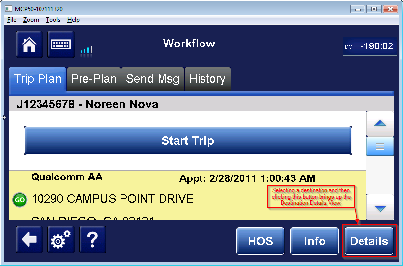
This view contains all the information for the Trip Plan and lists the Destinations in order. If the Trip Plan contains the datum beginEndTripEnabled and it is set to the value true, then the "Start Trip" and "End Trip" buttons will also be displayed. This view is defined in the following file: ..\eDriverWorkflowWinformsUI-TL\TripPlanPaginatedListView.cs. It is not recommended to edit this file.
• Destination Details View:

This view contains all the information about the Destination. The stop type determines what default tasks are assigned to this destination. The destID is the alphanumeric unique identifier of each destination. The order of the destinations is defined in the trip plan, by the sortID of the destination; each destination must have a unique sort ID. The destName is the assigned name of this destination (for example, Walmart). The address is split in the street address (the datum is called address, in the trip plan), the city (datum is called city, in the trip plan), state (datum is called state, in the trip plan), and the zip code (datum is called postalCode, in the trip plan). The customerID is the unique identifier for this customer. This value is set in the trip plan itself, for each destination. This view is defined in the following file: ..\eDriverWorkflowWinformsUI-TL\Views\ DestinationDetailsView.cs. Destinations are defined in the following file: ..\eWorkflowApplicationToolkit\Destination.cs. Below are the types of stops and their descriptions:
o Origin is used to record a stop at the origination shipper.
o Interline Pick-up is used to record an intermediate pick up stop between Origin and Final Destination (aka Terminal Finish).
o Pick-Up Relay is used to record a Relay stop where the driver picks freight that has been dropped off by an earlier driver, before proceeding to the Final Destination.
o Interline Drop-off is used to record an intermediate delivery stop, prior to the Final Destination.
o Dropoff Relay is used to record a delivery stop.
o Final Destination is used to record the end of the trip, typically at the distribution center. In some cases, this will be the ending point of the trip for the driver.
Note that only one Origin stop and only one Final Destination stop can be set.
• Task List View:
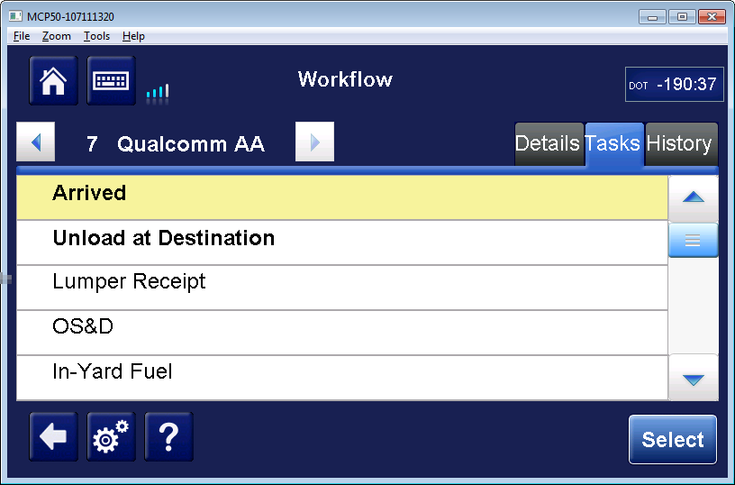
This view contains the tasks for a specific destination. A task is selected using the "Select" button, and is considered completed when the form for that task form has been submitted. Completed tasks have a green check mark next to them. This view is defined in the following file: ..\eDriverWorkflowWinformsUI-TL\Views\TaskListView.cs. Tasks are defined in the following file: ..\eWorkflowApplicationToolkit\Task.cs. Below is a list of the valid task types:
o arrived
o departed
o hook
o hookReefer
o drop
o dropReefer
o inYardFuel
o inYardFuelReefer
o inYardDelay
o pickupCustomerLiveLoad
o dropoffCustomerLiveUnload
o loadAtShipper
o loadAtShipperReefer
o unloadAtDestination
o unloadAtDestinationReefer
o reusables
o checkIn
o startWaiting
o startLoading
o startUnloading
o beginTrip
o endTrip
o delay
o weight
o fuelPurchased
o fuelPurchasedReefer
o obtainSignature
o delivery
o tripReview
o osd
o returns
o break
o freeFormMessage
o lumperReceipt
o layover
o accident
o breakdown
o storeCleanUp
o reportTemperature
o fuelRequest
o mailBag
o updateHoursAvailable
o tankWash
o scan
o video
o pickupRelay
o pickupRelayReefer
o dropoffRelay
o dropoffRelayReefer
o pickup
o pickupReefer
o dropoff
o dropoffReefer
o equipmentCheck
o unloadingInformation
o loadCompartment
o unloadCompartment
o reportExpense
o requestFuel
Note: The Final Destination does NOT have a departed task.
• PrePlan View:
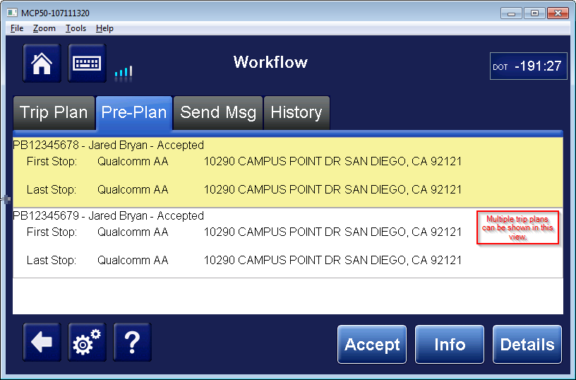
PrePlans are presented in this view. The user can click the "Accept" button to accept a PrePlan, info to see basic details of a PrePlan, and details to see the PrePlan as Destinations (each Destination also has its own details, tasks, and history). This view is defined in the following file: ..\eDriverWorkflowWinformsUI-TL\TripPrePlanListView.cs.
• Send Msg View:

The Send Messages view allows certain workflow tasks to be sent independent of the task list view. In this way, the driver can notify the dispatcher of "unplanned tasks", such as a delay or a fuel purchase. This view is defined in multiple files within the following folder: ..\eDriverWorkflowWinformsUI-TL\Views\SendMsg.
• History View:
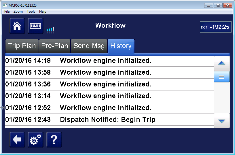
This view presents Workflow history events. This view is defined in the following file: ..\eDriverWorkflowWinformsUI-TL\HistoryListView.cs. History list items are defined in the following file: ..\eWorkflowApplicationToolkit\HistoryItem.cs.
Example Workflow Task
The process of the "Load at Shipper" task will be detailed below. The different tasks have different processes, but this example will give an idea of how Workflow works and aid the user is other Workflow tasks.
1. Select the details button when the first destination is highlighted.
2. Click on the tasks tab.
3. Click on the "Load at Shipper" task and press the "Select" button.
4. Fill out the "Load at Shipper" form, page 1. Click "Next Page" to continue.
5. Fill out next page. Click "Done".
6. The next mandatory task should load.
Scanning
Scanning is a task in Workflow. However, unlike other tasks, scanning also uses the Scanning Application. This process is detailed below.
1. Select the details button when a destination is highlighted. Click on the tasks tab.
2. Click on a Scan task and press the "Select" button. The Scanning application will open.
3. Select the Scanner and Document Type. Scan the document by selecting "Scan Page".
4. Scan multiple pages by selecting "Add Page".
5. Click the "Done" button when you have finished scanning.
6. Click "Send" button to send the document.
7. The device will now return the user to the Workflow application.
Signature Capture
Signature capture is a feature of Extended Productivity. As such, this feature requires that the user has an Android device with the Extended Productivity app downloaded.
• On handheld device:
1. Open the EP app.
2. Ensure that the Android is connected to the MCP/IVG device via Bluetooth pairing.
3. Hit the "Signature" button.
4. Use finger or device stylus to grab the signature.
5. (Optional) Fill in the consignee and/or notes.
6. Click the Check Mark to finish capturing the signature.
7. Click on the "Sync" button, to sync the signature capture to the MCP/IVG's trip plan.
• On MCP/IVG:
1. Select the details button when a destination is highlighted. Click on the tasks tab.
2. Click on the Signature Capture task and press the "Select" button. The Scanning application will open.
3. Ensure the Scanner is "EP Device" and Document Type is "Signature Capture". Then select "Scan Page".
4. Select the signature file, which was sent from the handheld device. Zoom out to verify that the signature is correct.
Note that there will only be a single signature capture listed. If two signatures were captured, only the most recent will be available.
5. Click the "Accept" button. The file will be loaded as a normal scan.
6. Follow steps #5 through #7 in the scanning section above.
Simulating Data
Data can be simulated to the unit using the command line interface (aka "CLI"). To use CLI, do the following:
1. Either use the unit's CLI dashboard app (enabled via Mongoose) or use telnet to connect to the device.
2. Put eMashT.exe on the device. (This program can be found at \\SAMUELB\Dropbox\eMAShT.) It goes in the following directory: ../IFlash.
3. Use the command "CD IFlash" and then the command "eMashT". eMashT will now start.
4. After eMashT has loaded, type the command "load_module WorkflowLoaderApplication.WorkflowLoaderAppCliModule WorkflowLoaderApplication.dll" and then the command "load_module TripManagerApplication.TripManagerAppCliModule TripManagerApplication.dll".
5. Type "help". This will display all the commands available from currently loaded CLI modules and what those commands do. Workflow specific commands are listed under "#tripmanager" and "#workflow".
Unit NVRAM Reset
If the unit is reset in Diagnostics and "Clear NVRAM" checkbox is selected, then the AppData is also reset. This means that Workflow template files are also erased. You will need to resend the Workflow template files to the unit after a NVRAM Reset. This also will resend CDEFs, so any Workflow settings will be reverted.
AppTest
AppTest is a software simulation that details most of the functionality of the Workflow app. Workflow changes can be tested first in AppTest. Note: AppTest does NOT have all of the functionality of the MCP50/IVG; it only has functionality specific to Workflow. Below are the steps to build, run, and use AppTest.
• MCP50 AppTests-TL:
1. Ensure that the eTIU solution has been built. Also ensure that the eDriverWorkflow-TL solution has been built.
2. Open the AppTests-TL solution. It is found at the following directory: ..\mobile\apps\mcp50\latest\SW\UnitTests\AppTests.
3. Ensure that TestAppDriver project is set as the startup project. To do so, right click on the project and click "Set as StartUp Project".
4. Click the Run button to run the AppTests-TL program.

• IVG oAppTest-TL5:
1. Ensure that the oTIU solution has been built. Also ensure that the oDriverWorkflow-TL solution has been built.
2. Open oAppTest-TL5 solution. It is found at the following directory: ..\mobile\apps\OTIS1.0\latest\SW\UnitTests\AppTests.
3. Ensure that TestAppDriver project is set as the startup project. To do so, right click on the project and click "Set as StartUp Project".
4. Find the project "oVIRFunctionalTests", which is located in the directory: ../Tests/FunctionalTests. Right click on this project and select "Unload Project".
5. Click the green "Start" button to run the oAppTest-TL5 window.

Other Workflow Resources
[Workflow PRD|https://omnitracs.sharepoint.com/sit...spx?sourcedoc=
Unknown macro: {A2A90742-BE2F-4DE5-8EBD-66AE5F5D4DF7}
&file=Workflow%202_0%20PRD%20V4_0.docx&action=default]
[Workflow SSD|https://omnitracs.sharepoint.com/sit...spx?sourcedoc=
Unknown macro: {D925C71B-9484-4D8B-B3D9-FD64BC9FE518}
&file=80-JB953-1_B.docx&action=default]
Perforce Workflow Docs:
../mobile/docs/DesignDocs/Apps/Workflow/