Omnitracs One 5.9 New Features and Enhancements
Overview
The Omnitracs One 5.9 release is available and includes new features, enhancements, and software corrections.
New Features and Enhancements
Important Information for Active Alert Users: Due to recent enhancements, you can no longer modify Active Alert settings in Omnitracs Client. All modifications to Active Alert settings are now performed in Omnitracs Web.
Routing
- You can add a layover to a route template where the driver is allowed to choose where the layover occurs.
- You can now open a picklist showing the stops or routes selected on the map.
Navigation
- A large number of screens have been enhanced for portrait mode. Screens that have been updated include the search page, quick menu, and numerous settings pages. Also, various pages related to POIs are now available in portrait mode.
- The feedback process has been streamlined, making it easier for the driver to report a problem to Omnitracs. Driver Feedback has been renamed to Report a Problem.
- You can now download maps from a san disk card and choose where the map data is stored.
- Omnitracs Navigation is now available in 64 bit. Previously only available as 32 bit, the application is now available as 64 bit from the Google Play Store.
- You can now specify if the driver is able to choose if the maps should be stored internally on the mobile device or on an external card, and if the driver is able to delete maps.
- The Region - Map Dataset Regions page has been renamed the Region - Map Download Options to better reflect the new options available.
- The ability to perform initial map downloads and quarterly updates is now available using an Ethernet connection.
Telematics
- You can add a binary sensor Telematics accessory to monitor the state of things like if a door is open or closed on the equipment.
- A new column has been added to Telematics Diagnostics. The Shared by Region column displays the ID and description of the first region the device is shared to; hover over the column to see a list of all regions the device is shared to.
- You can monitor where your equipment has traveled using Equipment History.
- The Telematics Devices window has been modified to make it easier to differentiate between Omnitracs devices and third party devices.
Safety
- You can now use in truck cameras to monitor accidents and other critical events, and review that video when needed.
Performance Monitoring
- There is a new Performance Monitoring component in Omnitracs Web that makes it easy to track your fleet's performance.
- There is a new Performance Monitoring report that provides performance information for your fleet.
- There are new Performance Monitoring measures and template KPIs in Insight.
Dispatching
- The ability to insert reload depots on routes has been added to Omnitracs Web.
- The ability to add unserviceable stop reason codes has been added to Omnitracs Web.
- In Autonomous Optimization, you can now require that stop resequencing and order assignment suggestions are approved.
- In Autonomous Optimization, you can easily see which routes have optimization turned on and which require attention in Fleetview.
- In Autonomous Optimization, dispatchers can approve or reject pending optimization suggestions for routes in Fleetview.
- In Autonomous Optimization, you can see details about a route's optimization suggestions on the Optimizations tab in Route Details.
- In Autonomous Optimization you can turn optimization suggestions on or off for a specific route in the mobile application.
Compliance
- More Hours of Service information has been added to the Worker's grid, Route Card, and Route Details header in Fleetview.
- If you are eligible, you can now enable the Canadian 14/180 Fertilizer Hrs rule for a region or a worker.
-
In compliance with FMCSA guidelines, Omnitracs XRS Mobile now inserts an automatic duty status annotation in the eRODS file when a driver switches from primary driver to co-driver and vice versa. When a primary driver switches to being a co-driver, the annotation for the most recent duty status change will note that the driver was “Removed as Active Driver [Date Time].” When a co-driver switches to being a primary driver, the annotation reads “Assuming Role as Active Driver [Date Time].” This annotation only appears in the eRODS file; it is not visible to drivers or back-office users. This change was made in response to guidance from the FMCSA to all ELD vendors with the goal of making behavior consistent across all ELDs.
-
If a driver’s vehicle is currently in motion and there has been no change in duty status and no intermediate event has been created for the driver in the previous hour, an intermediate event will be created regardless of the driver’s current duty status. This behavior also applies to co-drivers, ELD Exempt drivers, and drivers of AOBRD and ELD vehicles. This change was made in response to guidance from the FMCSA to all ELD vendors with the goal of making behavior consistent across all ELDs.
Active Alert Web Application
- You can add a photo to a worker's profile in Omnitracs Web, so customers using the Active Alert Web Application can identify the worker servicing their location.
- In Omnitracs Web, active alert settings for the business unit have been moved into region settings, to enable individual region settings. These settings have been removed from Omnitracs Client.
- You can create color schemes for the web application and assign them to individual regions, so each region can have a web application with a configured appearance.
- You can see a preview of your configured web application, after you save your active alert profile.
Strategic Planner
- You can assign sequential route IDs to selected routes, or sequential territory IDs to selected territories.
- You can easily assign workers and equipment to territories.
- You can now create service pattern sets that are based on the number of days between deliveries, instead of the number of weeks between deliveries.
- You can have reloads automatically generated when you run Create Strategic Routes.
- Several enhancements were made to Export Planning Solution to allow you to export additional data.
- A new report has been added to Strategic Planner that shows license usage by region
- If you drop a stop or recurring order on a day button on the map, and no route currently exists for that day, a route will now be created. In order for a route to be created, the recurring order must be assigned a Weeks Between Service service pattern set, and the service pattern set must contain a service pattern that allows a route on that day of the week.
Insight
- You can apply the absolute value function to your custom measure.
- You can now reset your KPI back to the original column order, after making changes to the column order in grid view.
- You can choose the label that displays on a chart or graph that uses a custom measure.
Drive/Command
- Updates have been made to Drive and Command to allow data to be seen in FleetView.
AMG-C
- The AMG-C will now use satellites to transfer information if a cellular network is not available.
Miscellaneous
- You can edit hazardous material classifications on street segments.
- The Edit Street Attributes notebook was rearranged, and a new page was added - Travel Info. Some information that affects road restrictions, such as speed, height, and weight, have been moved to this new page.
- A region's audit trail now includes who deleted the region, and when it was deleted.
- If you use unplanned routes, you can now associate a route ID with the equipment to make it easier to identify that equipment's routes.
There were several software corrections made in the Omnitracs 5.9 release.
Routing
Adding a Driver Selected Layover to a Route Template
Found in Omnitracs Client
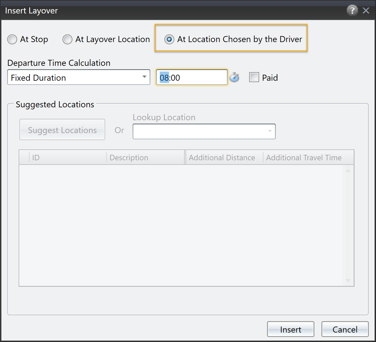
When you add a layover to a route template, you can specify that the layover should occur at a stop or a specific layover location. But, what if you want the driver to be able to choose where the layover should occur? Now, you have the option to add a layover where the driver can choose the location.
- On the Route Template manifest, double click on the route template you want to add the layover to. The route template stop list opens.
- In the route template stop list, right click on the stop that should precede the layover and choose Insert - Layover Template. The Layover Template window opens.
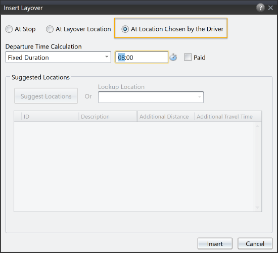
- Click At Location Chosen By Driver. Choose the Departure Time Calculation and, if necessary, enter the appropriate time. Check Paid if the driver is paid for the layover.
- Click [Insert] to insert the layover template.
Showing Items Selected on a Map
Found in Omnitracs Client
If you have several items in close proximity on a map, it can be difficult to determine which items you have selected, or even to make sure you have selected the proper ones. For instance, if several stops are grouped close together on the map, you can easily select the wrong stop without realizing it. Now, you can open a pick list that shows the stops selected on the map, and select the stops you want to work with. Some points about the pick list:
- The Route Planning, Route Dispatching, and Route Query maps each have two pick lists - one for selected routes, and one for selected stops and unassigneds.
- The Route Template map has two pick lists - one for selected route templates and one for selected stop templates.
- To select/deselect items for the pick list, click on them on the map. You can also use the lasso to select items on the map.
- To deselect items on the map from the pick list, click on the item on the pick list, then click [Update Map Selection] at the bottom of the pick list.
- As you select stops or routes on the map, the appropriate pick list will be updated. You can not select routes/route templates and stops/stop templates at the same time, either routes/route templates or stops/stop templates can be selected.
- The pick list contains the same columns as the corresponding list. For instance, the stops pick list contains the same columns as the stop list.
- The normal actions for an item are available from the pick list. For instance, the appropriate context menu is available from the pick list, so right-clicking a stop on the pick list opens the stops menu. You can also drag and drop items to and from the appropriate pick lists.
- Mid route depots, layover locations, and maintenance locations will not appear on the pick lists.
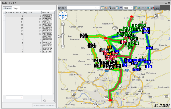
To open the pick list, click the Pick List icon on the map's toolbar. The pick list opens as a panel on the left edge of the map.

Here is an example of a pick list with several stops selected.
Navigation
Quickly Report A Problem in Navigation
Found in Omnitracs Navigation
Previously called Driver Feedback, the name of the feedback feature has changed to Report a Problem. This can be seen on the Main Menu and the Quick Menu. Not only has the name changed, the feature has been streamlined, so the driver can quickly add an issue, with fewer pages to move through, before tapping [Send] on the same page.
As before, when the driver taps Report a Problem from the menu, the first page allows the driver to add a new problem or edit an incident that was added from the Quick Menu. The updated details screen displays. Now, the details screen includes all the fields that are necessary to complete and send an incident. For each field, Problem type, Location, and Date and time, the driver taps the edit icon and chooses the appropriate answer. Then, the driver enters a brief description of the problem in the comment field. When the driver taps send, the issue is sent to Omnitracs.
Managing Map Data
Found in Omnitracs Navigation
Enhancements have been made to Omnitracs Navigation map data management. Enhancements include that map data can now be stored externally, on a san disk, also known as an SD card, the worker can choose which maps to use when map data is stored in two separate locations, and map data can be deleted from the mobile device.
Note: It is recommended that you use a Class 10 SD card with 16GB of storage.
When Navigation is first installed on the device, if map data is not found where it is typically stored, the worker is given the option to select the location of the map data, Internal or External. The Internal location may be the Routenet10 directory or another directory in the mobile device's storage area. If the worker chooses External, Navigation looks for an SD card and then searches the card for the map data. Once the map data is located, the Map Download screen displays and the worker either chooses which maps to install or the maps that are set for the region install. If necessary, the worker can tap the Storage Location edit icon and change where the maps are stored.
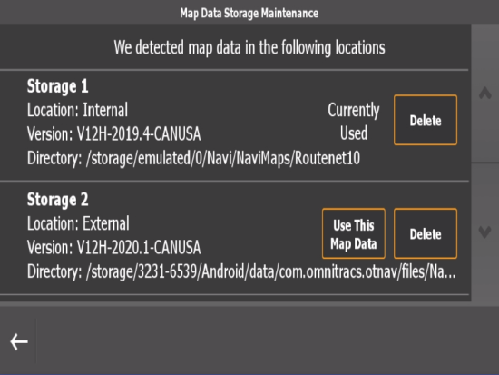
Another enhancement for managing the map data is the addition of Map Data Storage Maintenance. Now, Navigation can determine if more than one set of maps is available to the application. Information about the maps displays, based on the storage location. The worker can see the Location, Version of maps, and the Directory where the maps are stored. The worker can choose to use a different set of maps by tapping Use This Map Data. The worker can also choose to Delete a set of maps. At any point, when a change is made, the worker is prompted to confirm that they really want to make that change.
New Permissions for Drivers
Found in Omnitracs Web
Map data can be very large, and can consume a lot of storage space on the mobile device. Now, you can give drivers the option to store the maps on an SD card or other external area, freeing up space on the mobile device for other necessary applications.
If you want drivers to be able to manage the maps on their devices, you need to give them permission.
- Click on the Administration icon to open Administration.
- Click on the green button and scroll to Regions. The Regions list opens.
- In the left panel, click on Omnitracs Navigation, then Map Download Options. The Map Download Options page opens.
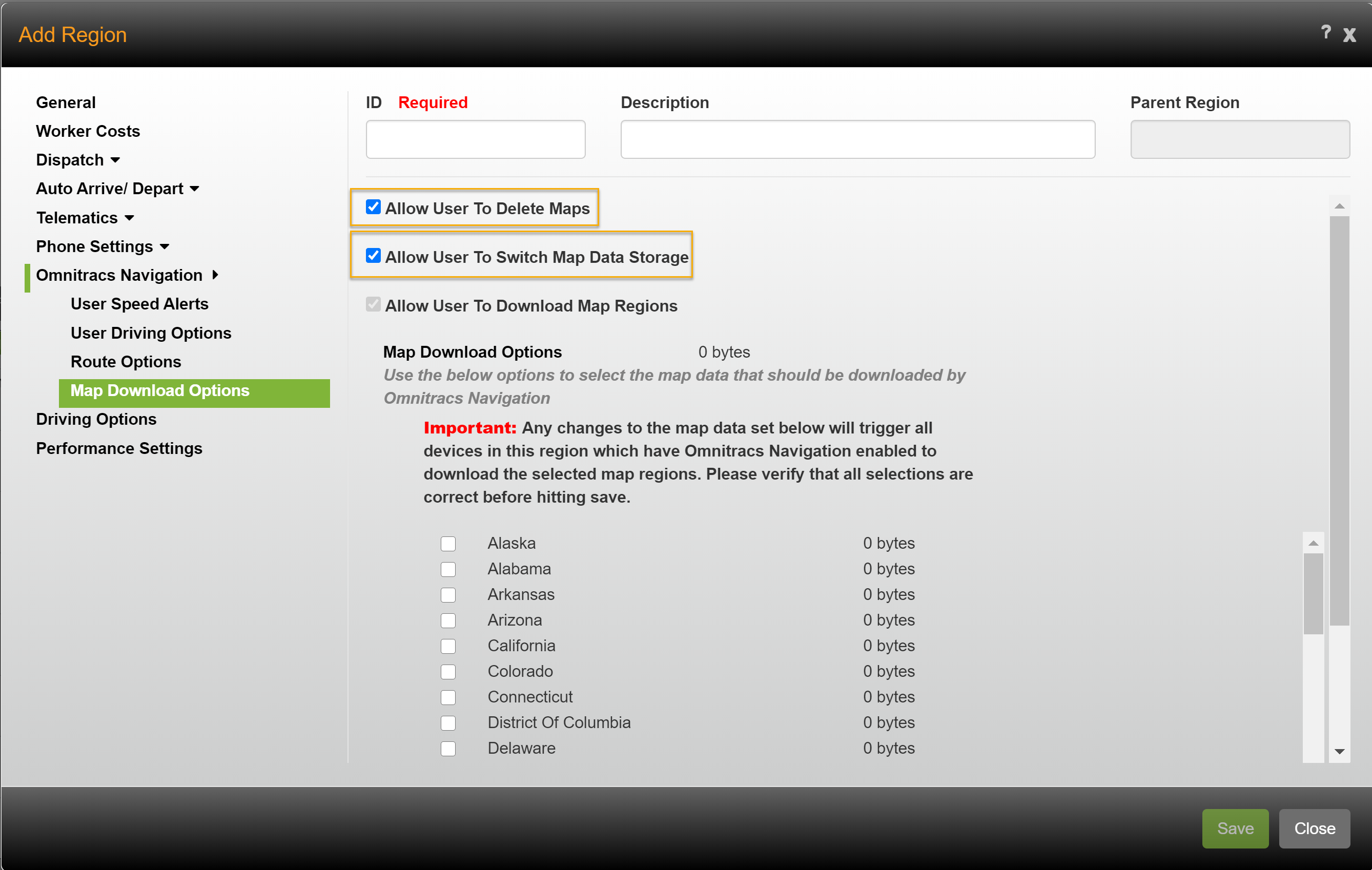
- To allow the driver to delete maps on the device, check Allow User to Delete Maps.
To allow the driver to store the maps externally, check Allow User to Switch Map Data Storage. - Click Save.
Safety
Viewing Critical Events
Found in Omnitracs Web
When accidents or other critical events happen to your drivers on the road, it may be important for you to be able to actually see what happened. You can place cameras in your trucks to video all actions that occur so that you can see what actually happened. When the Telematics device senses a critical event has occurred, it will automatically send the video of that event to the server so it can be reviewed. In addition, you can allow users to request video for other times if there is something that needs to be reviewed.
There are several items you need to set up to be able to view critical event videos:
- Each role needs to have the proper critical events permissions assigned
- Each region needs to be configured to use cameras
- Cameras need to be added to Omnitracs
- Cameras need to be assigned to the equipment
Setting the Permissions
In order to use critical event video, the role must be given permission. There are several levels of permissions for CEV.
In Omnitracs Web
- Click the Administration icon, then click the green button and select Role.
- Click Add; the Roles window opens.
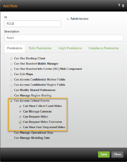
- On the Permissions page, check Can Access Critical Events. The permissions specific to CEV appear. Check the proper permissions for the role. The available permissions are:
Can View Critical Event Video - the role can click the link in the Critical Event Report to view videos.
Can Manage Cameras - the role can add, edit, or delete cameras in Omnitracs, as well as associating cameras to equipment
Can Request Video - the role can request videos from the Manage Video Requests page in the Safety component.
Can Request Video Extension - the role can request prequel and sequel video to the video requested in Manage Video Requests in the Safety component.
Can View User Requested Video - the role can view videos requested in the Safety component.
- Complete the remaining information for the role, then click the [Save] button.
In Omnitracs Client
- Click on Administration and scroll to Roles. The Roles list opens.
- Click on the Add icon. The Roles window opens.
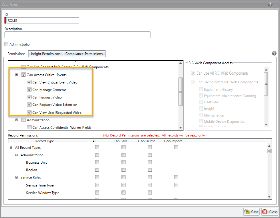
- On the Permissions page, check Can Access Critical Events. The permissions specific to CEV appear. Check the proper permissions for the role. The available permissions are:
Can View Critical Event Video - the role can click the link in the Critical Event Report to view videos.
Can Manage Cameras - the role can add, edit, or delete cameras in Roadnet Anywhere, as well as associating cameras to equipment
Can Request Video -the role can request videos from the Manage Video Requests page in the Safety component.
Can Request Video Extension - the role can request prequel and sequel video to the video requested in Manage Video Requests in the Safety component.
Can View User Requested Video - the role can view videos requested in the Safety component.
- Complete the remaining role information, then click the [Save] button.
Configuring CEV
Before you can start using CEV, you need to determine the resolution and length of the videos that will be uploaded, as well as what events will cause a video to be uploaded. This is done as part of the Region settings.
In Omnitracs Web
- Click on the Administration icon, then click the green button and scroll to Regions. The Region list opens.
- Click the Add button; the Region window opens.
- Click Video in the list on the left. The Video page opens.
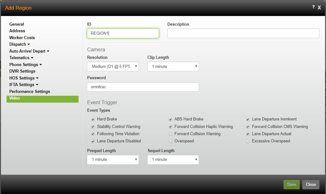
- Choose the options that define the camera operation.
Resolution - click the arrow and choose the resolution the videos should be recorded at.
Clip Length - click the arrow and choose the length of the clip to upload for the critical event.
Password- enter the wifi password for the camera to connect to the tablet.
- In the Event Trigger area, check the Event Types that are considered critical events, and will automatically cause a corresponding video to be uploaded.
- If you want video from before or after the critical event to be uploaded, click the Prequel and/or Sequel arrow and choose the proper length of time for each.
- Complete the remaining options for the region, then click the [Save] button.
In Omnitracs Client
- Click on Administration and scroll to Regions. The Regions list opens.
- Click on the Add icon. The Regions window opens.
- Click the Video Settings tab to open the Video Settings page.
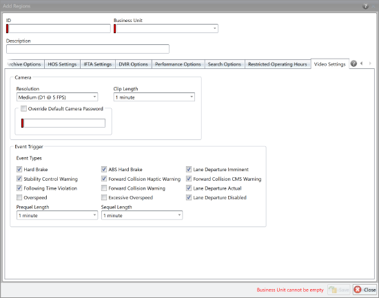
- Choose the options that define the camera operation.
Resolution - click the arrow and choose the resolution the videos should be recorded at.
Clip Length - click the arrow and choose the length of the clip to upload for the critical event.
Password- enter the wifi password for the camera to connect to the tablet. - In the Event Trigger area, check the Event Types that are considered critical events, and will automatically cause a corresponding video to be uploaded.
- If you want video from before or after the critical event to be uploaded, click the Prequel and/or Sequel arrow and choose the proper length of time for each.
- Complete the remaining options for the region, then click the [Save] button.
Adding the Cameras
You need to add your cameras that you will install in your equipment to Omnitracs. The cameras you add can be assigned to any equipment in the business unit.
Note: If there will be two cameras in the equipment, you will only add the camera that will communicate with the tablet.
- Click the Maintenance icon, then click the green button and scroll to Cameras. The Cameras list. opens.
- Click the Add button. The Camera window opens.

- Enter a unique ID for the camera.
- Enter the SSID for the camera. The SSID is the camera's wifi name.
- If there is a second camera that will be used with this camera, check Driver Facing Camera Enabled.
- Check Camera Audio Enabled if you want the camera to record the audio, as well as the video.
- Click the [Save] button.
Assigning the Camera to Equipment
Once you have added the cameras to Omnitracs, you need to assign the cameras to the equipment they are installed in, so that the proper video is associated with a critical event that happens.
Note: You can not assign a camera to the equipment until the equipment has been saved.
- Click on the Maintenance icon, then click on the green button and scroll to Equipment.
- Click the [Add] button; the Equipment window opens. Enter the proper information for the equipment. Click the [Save] button to save the equipment.
- Click the Edit icon for the equipment. The Equipment window opens.
- Click Camera to open the Camera page.
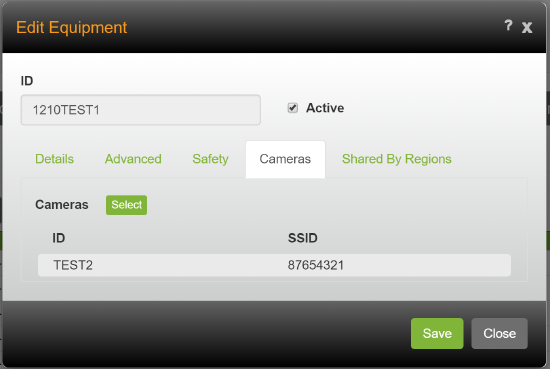
- Click the [Select] button. The Select Cameras window opens.
Note: Cameras already assigned to equipment will not appear in the Select Cameras window. Search is based on camera ID - Move the proper camera from the Excluded Cameras list to the Include Cameras list.
Note: If you need to filter the list of cameras to find the one you want to assign/unassign, start typing the camera's ID in the Type to Filter box; the list will be filtered to only those cameras that meet the filter criteria. - Click the [Save] button to return to the Equipment window. Click the [Save] button to save the equipment.
Viewing Video for a Critical Event
In Omnitracs Web
When the Telematics device detects that a critical event occurred on the road, the video from that event is automatically uploaded so that it can be reviewed. You can access the videos from the Critical Event report.
- Click on the Safety icon. The Safety component opens.
- Click Critical Events Report. The Critical Events Report Report Selector opens.
- Choose the Group By, Start and End Dates, and other criteria for the report, then click [Generate Report]. The Black Box Summary report opens.
- To view the video for a critical event, click the Video icon in the Action column. The Video Player opens. See Using the Video Player for more information.

Using the Video Player
The video player lets you easily review the video. There are many different ways to manipulate the CEV's playback window, from changing the data points overlay color, to changing the playback speed, to requesting additional event footage. Surrounding the actual video pane in the player are several tools that can help.
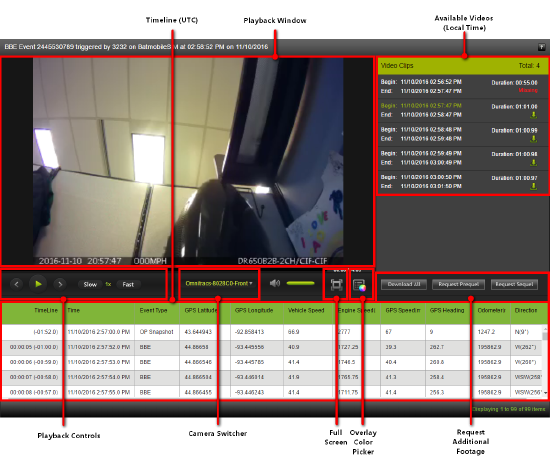
- Next to the video is a list of the available video clips. For each clip you can see the begin and end time, the duration of the clip and its current status. The status options are:
- Missing Video File: Indicates that the device tried to upload the file several times but failed because the file is missing.
- Fail Video File: Indicates that the device tried to upload the file several times but failed because of an issue with the file.
- Pending: Indicates that the video exists but has not been fully processed and uploaded yet.
- Begin: Indicates that the video file is uploaded and available to view.
You can also choose to see the video directly before or after the selected video by selecting the Request Prequel or Request Sequel buttons.
In a row under the video are several controls that you can use to control the video.
To play, pause, forward, or reverse the video, use the buttons on the control panel.
To switch to footage from the second camera in the equipment, click the arrow and choose the camera you want to view. This option is only valid if the equipment has both a forward facing (road) and backward facing (driver) camera, click the arrow to view footage from the other camera.
To have the video expand to fill the entire screen, press the Full Screen icon.
To change the color on the Heads Up display, click on the color picker and choose a color. The Heads-Up Display is an overlay which displays ongoing Vehicle Diagnostics such as Vehicle Speed, GPS Speed, Engine Speed, GPS Heading, Odometer, and Direction. The Heads-Up Display on the left side of the Playback Window displays Driver ID, Vehicle ID, Event Type, GPS time, Longitude, and Latitude.
Requesting Video for Non-Critical Times
In Omnitracs Web
If it is detected that a critical event has occurred, the video for that event is automatically uploaded. But, what if you want to review video for an event or time that is not deemed critical? You can request that video be uploaded for a defined time in the Safety component.
Note: You must have permission to request video for this functionality to be available.
Video is only stored on the camera for 30 days. Once this has passed, the video is no longer available to be requested.
- Click the Safety icon. The Safety component opens.
- Click Manage Video Requests. The Manage Video Requests page opens.
- Click the [Request Video] button. The Request Video window opens.
- Enter the equipment ID in the Assigned Vehicle field.
- Select the date and time you want video from.
Note: The video clip will be 60 seconds in length. - If necessary, enter the additional time you want for the video in the Prequel Length and Sequel Length. Enter this time in minutes.
Note: The total amount of requested time can not exceed 6 minutes. - Click the [Send] button.
Viewing Requested Video
In Omnitracs Web
You can view requested videos in the Manage Video Requests portion of the Safety component.
- Click on the Safety icon to open Safety.
- Click on Manage Video Requests. The Manage Video Requests window opens, listing requested videos.
- Find the video you want to view.
To limit the list of requested videos, making it easier to find the one you want, filter the list. To only see Pending or Received videos, click Request Status and choose the proper option. To only see videos for specific regions, click Organization, then select the regions you want to see videos for.
To search the list for specific videos, click the Search icon and enter the item you are searching for. Click the Organization arrow and choose what you are searching on - organization (region), driver ID or vehicle ID. - Click on the link to open the video player and view the video. See Using the Video Player for more information.
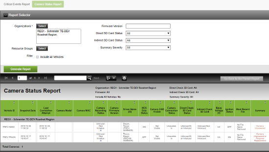
Determining the Status of your Cameras
In Omnitracs Web
At times, you may want to know the status of all your cameras that are currently connected, such as the firmware version and the SD card status, and a summary of the camera's status. You can see this information on the Camera Status report in the Safety component.
- Click on the Safety icon to open the Safety component.
- Click Camera Status Report; the Camera Status report selector opens.
- Select the Organizations that you want included in the report.
Note: Organizations are the regions you set up in the Administration component. - If you are using Resource Groups, select the resources groups to include.
- To include equipment that does not contain cameras in the report, check Include All Vehicles.
- To only include cameras with a specific firmware version, enter the version in the Firmware field.
- To only include cameras with a specific SD card status, click the appropriate SD Card Status arrow and choose the status.
- To only include cameras with a specific summary severity, click the Summary Severity arrow and choose the proper severity.
- Click the [Generate Report] button. The report appears below.
You can export or print the report.
Telematics
Using a Binary Sensor
Found in Omnitracs Client and Web
You may have conditions that you want to monitor on your equipment that are a true/false situation. For instance, you may want to know if the door is open or closed. Now, you can add a binary sensory to your Telematics I/O Configuration to help monitor situations like whether the truck door is open or not.
Note: Roadnet Telematics and the AMGC can use a binary sensor; the Relay can not use a binary sensor.
The first step in adding a binary sensor is to create the Telematics I/O Accessories.
- Click on the Maintenance icon to open Maintenance.
- Click on the green button and scroll to Telematics I/O Accessories. The list of all Telematics I/O Accessories opens.
- Click [Add] to add a new accessory. The Telematics I/O Accessory window opens.
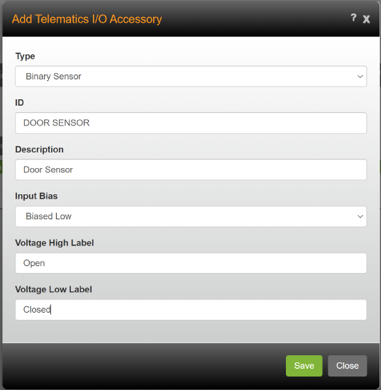
- Click the Type arrow and choose Binary Sensor.
- Enter an ID and Description for the sensor.
- Click the Input Bias arrow and choose whether the sensor is wired so that the default voltage is biased high or biased low.
- Enter the state that the high and low voltage should indicate in the Voltage High Label and Voltage Low Label.
- Click [Save].
Using Equipment History
Found in Omnitracs Web
There may be times that you want to see the position history of a piece of equipment for a period of time plotted on the map, as an easily understandable visual indicator of where the piece of equipment has been. Now, Telematics users can:
- Grant users permission to use Equipment History.
- Open Equipment History directly, or from screens in Telematics Diagnostics or FleetView.
- Search for a piece of equipment and view its position history on a map with information about its position at each point in time for a length of time that you specify.run a printable report that displays position history information such as the position time, location, ignition status, latitude and longitude, speed, and direction.
Granting Role Permissions to Use Equipment History
Found in Omnitracs One Web and Client
In order to use Equipment History, your role must have permission. When setting up a role, you can now grant permission to use this feature.
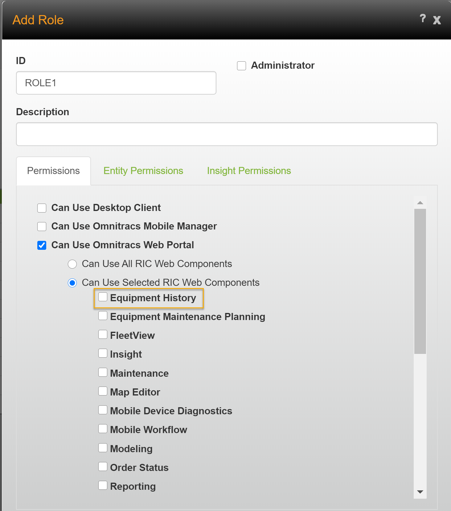
To set permission in Omnitracs One Web:
- Go to Administration, then click the green button and scroll to Roles.
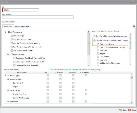
- Click the [Add] button or the Edit icon. The Add/Edit Role window opens.
- On the Permissions tab, check Can Use Selected RIC Web Components, then check Equipment History in the list of available RIC web components.
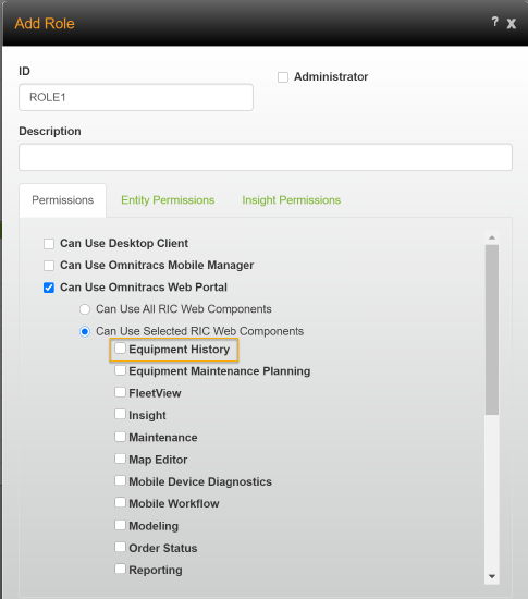
- Click the [Save] button.
To set permission in Omnitracs One Client:
- Click Administration and select Roles from the drop-down menu, or click the Roles icon from the toolbar. The Roles tab opens.
- Click the New icon. The Add/Edit Role window opens.
- On the Permissions tab, check Can Use Selected RIC Web Components under RIC Web Component Access, then check Equipment History in the list of available RIC web components.
- Click the [Save] button.

Opening Equipment History
Found in Omnitracs One Web
To open Equipment History directly, click on the Equipment History icon.

To open Equipment History from Telematics Diagnostics, click on the Equipment ID of the piece of equipment you want to see equipment history for. The Equipment History screen opens. Enter the start and end dates/times of the date range you want to see equipment history for.
To open Equipment History from the Overview in FleetView, click the Bars icon on a vehicle card and select Equipment History. The Equipment History screen opens. Enter the start and end dates/times of the date range you want to see equipment history for.
To open Equipment History from Routes Cards, Grid or Map, click on the Equipment you want to see equipment history for as it appears on the card or grid. The Equipment History screen opens.
To open Equipment History from the Equipment grid, click on the Equipment. The Equipment History screen opens.MARISA CHECK THIS
To open Equipment History from Route Details, click on the Equipment as it appears with the route information on the left side of the screen. The Equipment History screen opens.
Searching for Equipment
Found in Omnitracs One Web
- Go to Equipment History.
Note: Equipment History can also be accessed directly from Telematics Diagnostics and FleetView.
- Begin entering the equipment ID or description, Telematics device ID or description, or worker ID or name in the Search field to see a list of matching equipment. Select a piece of equipment from the list.
Notes: Only equipment with an associated Telematics device is returned in search results. - If searching by worker, only the preferred worker on the equipment can be located; likewise, if searching by Telematics device, only the Telematics device associated with the equipment can be located.
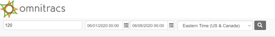
- Click in the Start Date/Time field and enter a start date and time, then click in the End Date/Time field and enter an end date and time.
OR
Click the calendar icon next to each field and select a date, then manually enter the time in 24-hour format in the field.
Notes: You cannot enter a future date or time.
The date range cannot exceed 8 days in duration. - Click the arrow in the time zone field and select the time zone you want to search in.
- Click on the Search icon to perform the search.
The history for the equipment is displayed. On the left is a list of cards with information about each ping that is shown on the map. On the right is a map showing the path of the equipment plotted in green arrows; each green arrow represents a GPS ping. The ID and description of the featured piece of equipment is displayed above the map to the left.
Using the Cards
Found in Omnitracs One Web
The ping cards show information about each GPS ping. Each ping on the map is represented by its own card.
On the cards you can see:
- the sequence number of the ping within the specified time range
- the date and time the ping was collected by the Telematics device
- a description of the equipment position
- the ignition state of the equipment (a blue power symbol indicates "on", a gray power symbol indicates "off", a question mark (?) indicates "unknown")
- the equipment speed as calculated by GPS
To see which ping on the map corresponds to a card, click on the card, a solid red marker is displayed over the corresponding ping on the map and the timeline marker will move to the time associated with the card. You can also hover your cursor over the card and a translucent red marker is displayed over the corresponding ping on the map.
Using the Map
Found in Omnitracs One Web
The map shows the path of the equipment. Pings at which the equipment is moving are represented by green arrows on the map. Pings at which the equipment is stationary are represented by a single blue circle. You can hover over a ping on the map to see the date and time, address, location description and nearby points of interest, speed, and ignition state of the piece of equipment. When hovering over a stationary icon you can also see the time frame of each ignition state during which the equipment was stationary. You can click on a ping or stationary icon on the map to be directed to the corresponding ping card and to move the timeline marker to the time of that event.
You can zoom in or out, or move around the map, to see more detailed information.
Notes: Depending on the level at which the map is zoomed in, plotted points may appear clustered. Zoom in further to see the individual pings in a cluster.
If you want to expand the map and timeline to fill the entire screen, click the Expand icon; the map/timeline fills the entire screen. To shrink the map/timeline back to its normal placement in Equipment History, click the Restore icon.
To zoom in or out, move the zoom bar slider up (zoom in) or down (zoom out).
To zoom in on a different area of the map, right click on that area and choose Zoom from the menu that pops up.
To move to a different area on the map, use the compass rose, or click and drag the map to show the area you want to see.
To move the map so it is centered on a different point, right click on that point and choose Center from the menu that pops up.
To fade the map background so you can see the route more clearly, slide the blue circle on the Fade bar in the top right corner of the map.
To switch the maps to satellite mode, click the arrow button and select Satellite. To change back to street mode, click the arrow button and select Streets.
To open a map in Bing or Google, so you can use the full features of those maps, right click on the map and choose Show Using, then Bing or Google. A new browser tab opens with the appropriate map.
To see the ping card that corresponds to a marker on the map, click on a map marker. The position list scrolls to the corresponding card, highlighted in a green border.
Note: If you click on a stationary position marker, the position list highlights the card corresponding to the first position in the stationary event.
Using the Timeline
Found in Omnitracs One Web
Beneath the map is the timeline, which allows you to easily see the length of stationary and travel periods of the equipment during the time range.
The different route components are displayed in different colors:
Stationary events are light blue rectangles.
Travel time is a green line.
Hints: You can hover over any of the events on the timeline to see more information about that event. If you click on a ping or stationary icon on the map, the timeline marker will move to the time of that event.
If you want to hide the route timeline, leaving more room for the map, click the Toggle Timeline icon. The timeline collapses; to restore the timeline click the Toggle Timeline icon again.
You can change the times shown on the timeline to see more or less detail.
To reduce the amount of time shown on the timeline, so you focus on a portion of the piece of equipment's time range, click the Zoom In icon or scroll the mouse wheel up.
To increase the amount of time shown on the timeline, click the Zoom Out icon or scroll the mouse wheel down.
To automatically size the timeline to show all events for the selected time range, click the Fit Events for Selected Date icon.
To move backward or forward in time, click the arrows.
To see the ping card that corresponds to a point on the timeline, double click on the timeline. The position list scrolls to the corresponding card, highlighted in a green border. A marker will also appear on the corresponding event on the map.
The timeline works in conjunction with the map; the map and the timeline are showing the same time range. To see more information about a particular event, simply hover over it on the map or the timeline and a tooltip pops up with more information describing the event. You can zoom and move around on the map as needed to see individual events more clearly.
The current time on the timeline is marked with a red balloon; there is a corresponding red balloon marker on the map. If you want to playback a route, to see where the equipment was at a given time, slide the red balloon back and forth along the timeline; the red balloon with the bulls eye on the map moves accordingly to show where the equipment was at that time.
Note: When the marker on the map follows a route, it moves from GPS marker to GPS marker. GPS pings and events that occur after the marker appear fainter than those that occurred before the marker.
Running the Position History Report
The Position History report displays position history information such as the position time, location, ignition status, latitude and longitude, speed, and direction, for a piece of equipment for a selected period of time. You can save this report as a CSV file, manipulate data as needed, and print the report.
To run the report:
- Click the Equipment Actions arrow and select Position History Report. The Position History Report window opens.
Note: If you have already selected a piece of equipment and time range in Equipment History, the fields in the Position History Report window are prefilled with that information and you can proceed to Step 5.
- Begin entering the equipment ID or description, Telematics device ID or description, or worker ID or name in the Equipment Search field to see a list of matching equipment. Select a piece of equipment from the list.
Notes: Only equipment with an associated Telematics device is returned in search results.
If searching by worker, only the preferred worker on the equipment can be located; likewise, if searching by Telematics device, only the Telematics device associated with the equipment can be located. - Click in the Start Date/Time field and enter a start date and time, then click in the End Date/Time field and enter an end date and time.
OR
Click the calendar icon next to each field and select a date, then manually enter the time in 24-hour format in the field.
Notes: You cannot enter a future date or time.
The date range cannot exceed 8 days. - Click the arrow in the time zone field and select the time zone you want to search in.
- Click [Run]. The report file appears at the bottom of the window. Click on the report to open it. From the open report you can print it or save it to view later.
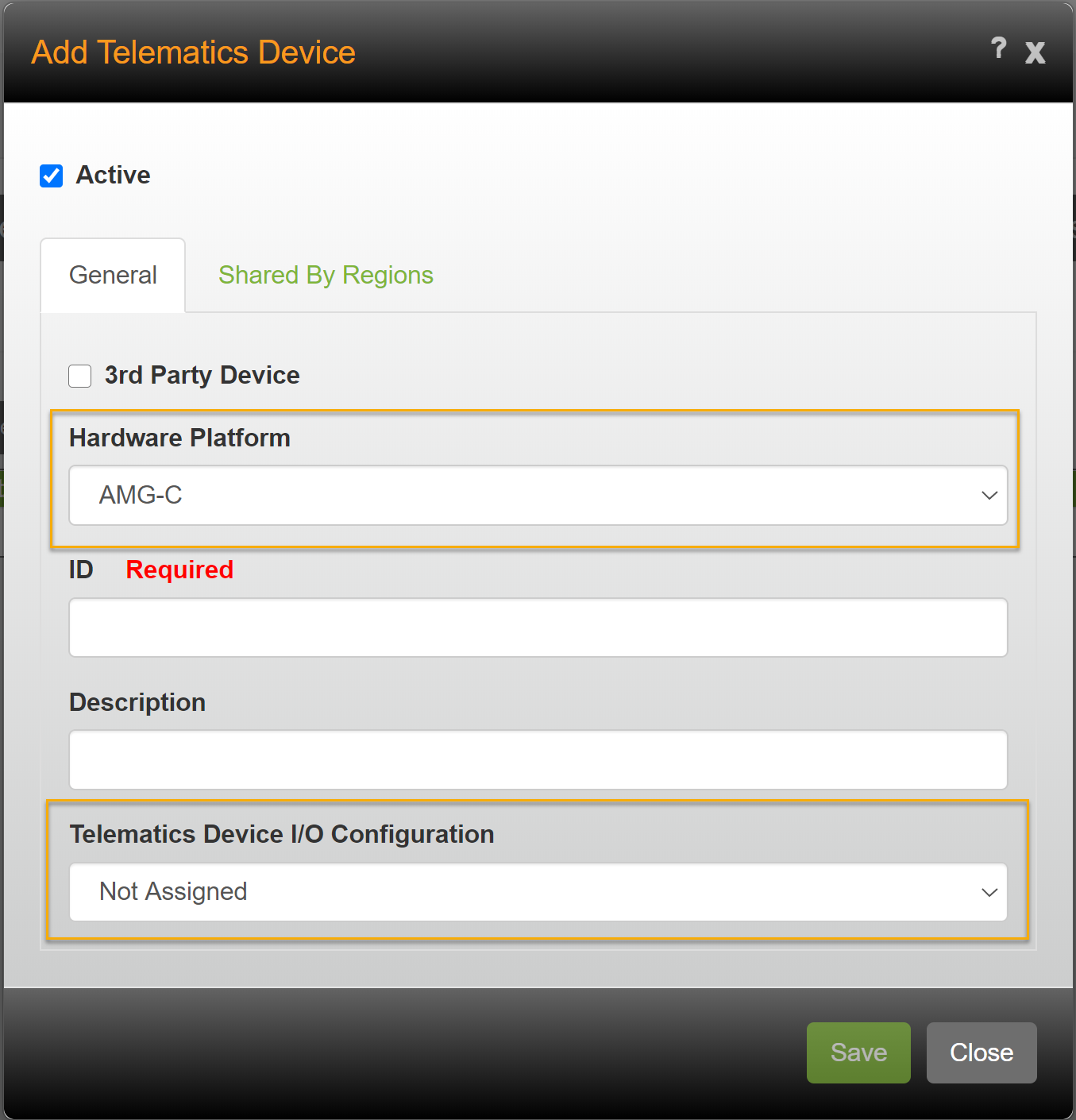
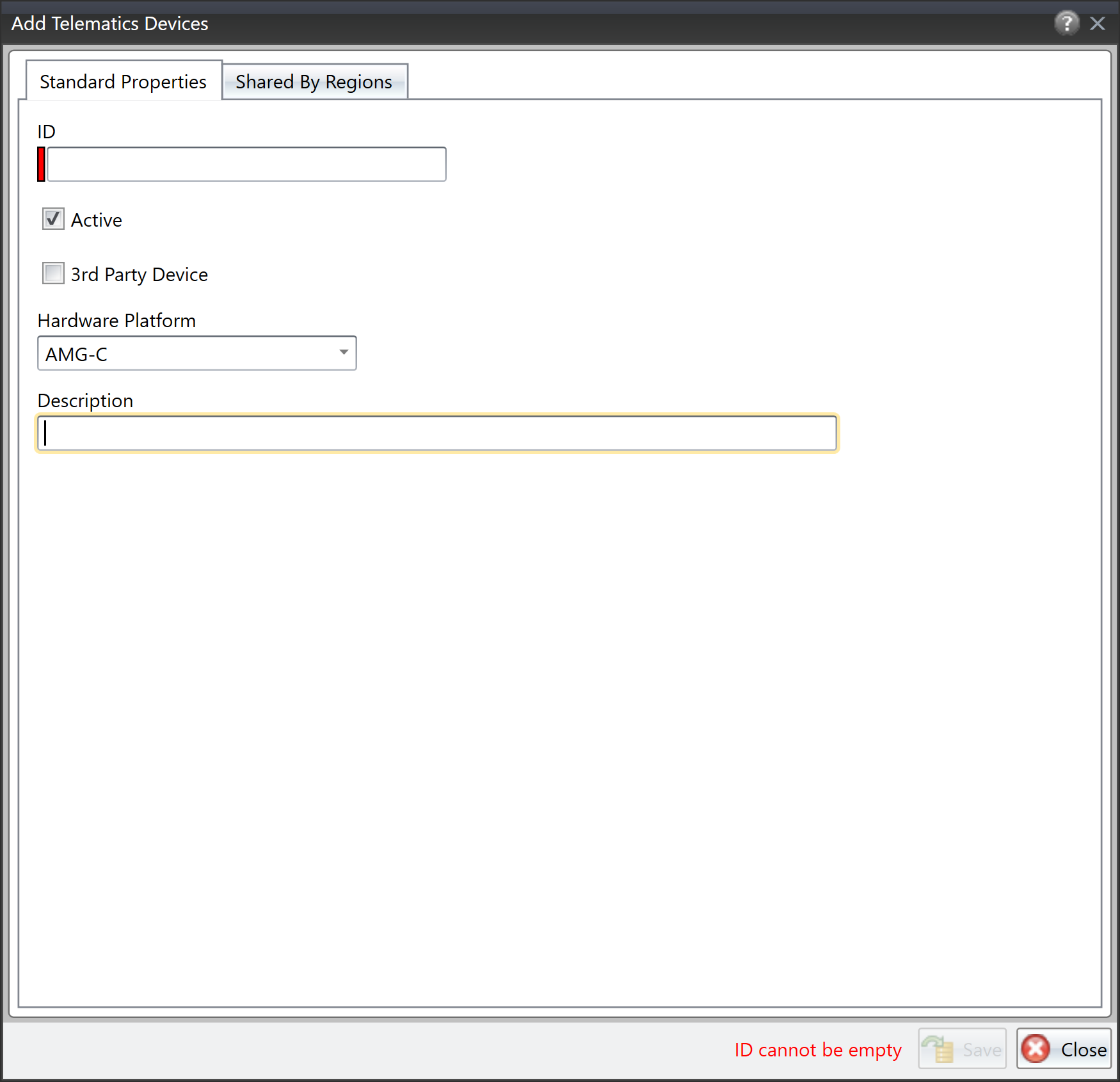
Changes to Adding Telematics Devices
To make it easier to add Telematics devices, the Telematics Devices window has been modified.
In Omnitracs Web
In Maintenance, click on the green button and scroll to Telematics Devices to open the Telematics Devices list. Click [Add]; the Telematics Devices window opens.
If adding a Roadnet Telematics, Relay, or AMG-C, make sure 3rd Party Device is not checked. Click the Hardware Platform arrow and choose the proper type. Enter an ID, Description, and it appropriate, choose the Telematics Device I/O Configuration. Click [Save].
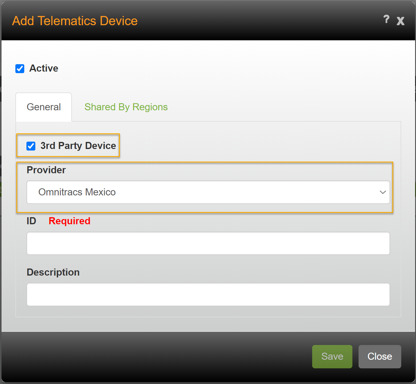
If adding a third party device, check 3rd Party Device. Click the Provider arrow and choose the proper type. Enter an ID and Description. Click [Save].
Note: Compliance customers who purchased the legacy XRS system should check 3rd Party Device and choose XRS as the Hardware Platform.
In Omnitracs Client
Click the Dispatching menu and scroll to Telematics Devices. The Telematics Devices list opens. Click the Add icon to open the Telematics Device window.
If adding a Roadnet Telematics, Relay, or AMG-C, make sure 3rd Party Device is not checked. Click the Hardware Platform arrow and choose the proper type. Enter an ID and Description. Click [Save].
If adding a third party device, check 3rd Party Device. Click the Hardware Platform arrow and choose the proper type. Enter an ID and Description. Click [Save].
Note: Compliance customers who purchased the legacy XRS system should check 3rd Party Device and choose XRS as the Hardware Platform.
Safety
Performance Monitoring
Found in Omnitracs Web
It is important for you to be able to monitor the performance of your overall fleet - the number of vehicles on the road, their fuel usage, mileage, hours, etc. - and even be able to drill in and investigate individual pieces of equipment. The new Performance Monitoring component in Omnitracs Web allows you to quickly and easily gather information on your entire fleet on one screen, instead of needing to print reports or analyze KPIs.
The top of the Performance Monitoring screen shows key data for the entire region, such as the total number of vehicles, total distance, time, and fuel, and overspeeding. At the bottom of the screen you can see detailed information either by worker or by equipment. To choose whether you want to see worker or equipment data, click the Group By button and choose Equipment or Worker.
Note: The summary at the top displays time in decimal hours, while the details grid displays time in hours and minutes.
When you first enter Performance Monitoring, it automatically shows information for the current day. To change the date, click the arrow next to the date to move backward or forward. Or, click the Calendar icon to open a calendar; click on the date you want to view.
You can filter, sort, or export the Details grid.
To filter the Details grid to only show selected data, enter the filter information in the column you want to filter on. The ID and Description columns will filter on the text you enter; simply start typing in the filter row to filter on that column. The remaining columns let you enter a numeric value and choose a comparison (equal, not equal, greater than, etc.) that must be met. For example, if you want to see only equipment that has longer routes, enter a number like 200 in the Total Distance filter, then click the arrow and choose Greater Than.
Note: If you filter on more than one column, only items that meet all the criteria will be displayed.
To sort the grid on a particular column, click the column header and choose whether to Sort Ascending (ABC) or Sort Descending (CBA).
To export the visible content in the grid to a .csv file, click the [Export] button. The .csv is downloaded to your computer.
The following information is available in the Details grid. It is also included in the Performance Monitoring report, and is available as the KPI measures in Insight.
| Field | Description |
|---|---|
| ID | The ID of the equipment or worker. |
| Description | The description or name of the equipment or worker. |
| Cruise Control Distance | The total distance the equipment was in cruise control. |
| Cruise Control Fuel | The total amount of fuel used while the equipment was in cruise control. |
| Cruise Control Time | The total time the equipment was in cruise control. |
| Driving Fuel | The total amount of fuel used while the engine was running but not idling for the day. |
| Driving Time | The total amount of time the engine is running and not idling for the day. |
| Excessive Overspeed Fuel | The total amount of fuel used while the equipment was the exceeding the Excessive Speed Threshold. |
| Excessive Overspeed Time | The total amount of time the equipment spent exceeding the Excessive Speed Threshold set on the equipment profile. |
| Fuel Distance | Distance used to calculate the MPG this would equate to the time the vehicle is moving (driving). |
| Fuel Economy | The average mileage the equipment had over the day, measured as either miles per hour (MPH) or kilometers per hour (KPH), depending on the selected Speed measurement unit. |
| Idle At Depot Fuel Used | Fuel used by the vehicle while idling at a depot (depot is defined by customer). |
| Idle At Depot Time | Time the vehicle is idling while at a depot (depot is defined by customer). |
| Idle Fuel | The total amount of fuel used while idling. |
| Idle Time | The total amount of time the vehicle was idling. |
| Moving Fuel | Fuel used while vehicle is moving (this would be the same as Driving Fuel). |
| Moving Time | Time while vehicle is moving (this would be the same as Drive Time). |
| Overspeed Fuel | The total amount of fuel used while the equipment was exceeding the Speed Threshold. |
| Overspeed Time | The total amount of time the equipment spent exceeding the Speed Threshold set on the equipment profile. |
| Park Fuel | The total amount of fuel used while the equipment was idling in park. |
| Park Time | The total amount of time the equipment was in park. |
| PTO Distance | Distance Traveled when PTO is engaged. |
| PTO Fuel | The amount of fuel used while the power take off (PTO) unit was running. |
| PTO Moving Fuel Used | Fuel Used when PTO is engaged and the vehicle is moving. |
| PTO Moving Time | Time when PTO is engaged and the vehicle is moving. |
| PTO Stationary Fuel Used | Fuel Used when PTO is engaged and the vehicle is not moving. |
| PTO Stationary Time | Time when PTO is engaged and the vehicle is not moving. |
| PTO Time | The amount of time the power take off (PTO) unit was running. |
| Top Gear Time | The total amount of time the equipment was operating in its top gear. |
| Total Distance | The total distance traveled on that day, measured as miles or kilometers. |
| Total Fuel | The total amount of fuel used that day. |
| Total Time | The total time the equipment's engine is running. |
New Performance Monitoring Report
If you want to see performance monitoring data for more than one region or one date, you can run the Performance Monitoring report. The report contains the data seen in the Details grid, such as driving and fuel information.
Note: The Performance Monitoring report is only available as a .csv report.
- Click the Reports icon to open Reports. Scroll to the Performance Monitoring report. The Options are visible.
- If you want to select the regions included in the report, click the Regions arrow and select the appropriate regions. By default, the current region is automatically selected.
- In the Criteria section, choose the start and end date for the report.
- In the Options area, click the arrow and choose whether the report should be grouped by Equipment, Worker or Region.
- Click [Run]. The report runs and is downloaded to the computer.
New Performance Monitoring Measures in Insight
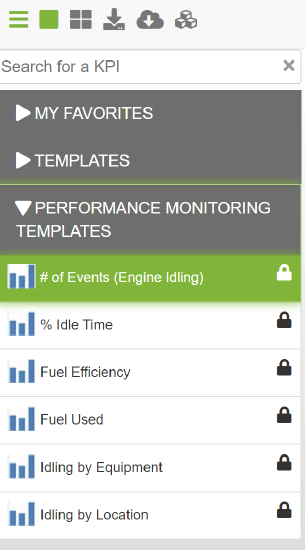
Insight comes with template key performance indicators (KPIs) that can help you analyze your data, but you can also create new KPIs to show data you are interested in. Often when creating a new KPI, you use measures to select the data you want to see. Several new template KPIs and measures related to Performance Monitoring are now available. The new template KPIs are:
- # of Events (Engine Idling) - shows the actual number of idling events, by region, for the selected date range.
- % Idle Time - shows the percent of time each worker spent idling for the selected date range.
- Fuel Efficiency - shows the actual miles per gallon per region for the selected date range
- Fuel Used - shows the total amount of fuel used per region for the selected date range
- Idling By Equipment - shows the actual amount of time spent idling per piece of equipment for the selected date range
- Idling By Location - shows the actual amount of time spent idling per location for the selected date range
The new Performance Monitoring measures are:
- Num of Events (Engine Idling)
- Num of Events (PTO)
- Engine Run Time
- Fuel Used (Cruise Control)
- Fuel Used (Engine Idling)
- Fuel Used (PTO in Motion)
- Fuel Used (PTO Stationary)
- Fuel Used (Total)
- Miles
- Miles (Cruise Control)
- Miles (PTO)
- Time (Cruise Control)
- Time (Engine Idling)
- Time (PTO in Motion)
- Time (PTO Stationary)
- Time (Top Gear)
Dispatching
Adding Unserviceable Stop Reason Codes
Found in Omnitracs Web
Unserviceable Stop Reason Codes are used to explain why a stop is marked as unserviceable by the worker. Unserviceable Stop reason codes are added in Omnitracs and sent to the mobile device, so that when the worker marks a stop as unserviceable, they can pick the reason why it was marked unserviceable from a list. Previously, the ability to add Unserviceable Stop Reason Codes was only available in Omnitracs Client. To make it easier for those who use Omnitracs Web, the ability to add Unserviceable Stop Reason codes has been added to Omnitracs Web.
To add an Unserviceable Stop Reason Code in Omnitracs Web, do the following.
- In the Maintenance module, click the green button on choose Unserviceable Stop Reason Codes.
- Click Add.
- Enter an ID and Description.
- Click Save. Repeat steps 2 - 4 until all reason codes are added.
Unserviceable Stop Reason Codes will now be required on the mobile device and in Fleetview when a stop is marked unserviceable.
Inserting Reload Depots to Routes
Found in Omnitracs Web
Mid-route depots, also know as reloads, are used to add depot stops to routes that finish early enough in the day to reload the vehicle and go out on another trip, or to refill the vehicle half way through the route, so that enough product is available to complete the trip. Previously, the ability to insert reload depots was only available in Omnitracs Client. To make it easier for those who use Omnitracs Web, the ability to insert reload depots has been added to Omnitracs Web.
To insert a reload in Omnitracs Web, do the following.
- If necessary, open Route Details for the route you want to work with. Route Details can be opened by clicking on the appropriate route in Cards mode or the Routes Grid.
- Check the box to the left of the the stop that you want to precede the reload depot.
- Click Route Actions, and then select Insert Reload from the list that displays. The Reload Stops window opens.
Notes: On the route details screen, you can right-click the stop that you want to precede the reload depot and select Insert Reload from the menu that pops up.
To insert a reload as the first stop on a route, right-click on the origin depot and select Insert Reload; the reload is placed after the origin depot. However, if Stop 1 has already arrived, you can't insert the reload after the origin depot.
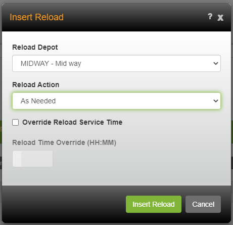
- Click on the Reload Depot arrow to open a list of existing reload depots. Click on the depot you want to add to the route.
- Click on the Reload Action arrow and choose an action from the list.
As Needed - equipment is only filled with product needed to complete the trip. This is the most common choice.
Full - equipment is completely refilled at the depot.
Empty - equipment empties entire load at the depot.
None - equipment returns to the depot, but not for loading or unloading. For example, the truck could return to be refueled.
- Select Override Reload Service Time if you want to override the service time calculations defined on the route's pass. In the Reload Time Override field, enter the amount of time needed to perform the necessary actions. Enter the time in the HH:mm format. This is a fixed amount of time.
Note: If Override Reload Service Time is not selected, the reload service time is calculated using the Reload Times configured on the pass. On the pass, you can configure fixed and variable times, or use the service times defined on the depot.
- Click [Insert Reload] to save the reload depot to the route.
A reload depot is added to the route.
Autonomous Optimization
Requiring Approval for Autonomous Optimization Suggestions
Found in Omnitracs Web
If your company is using Autonomous Optimization to improve route sequencing and assign unassigned orders, you know that workers are able to manage suggestions on the mobile device for stop resequencing or order assignments. Dispatchers are able to turn autonomous optimization off for a route, but they are not able to approve or disapprove a suggestion. Now, you can require that suggestions be approved by the driver or dispatcher before the route is actually changed.
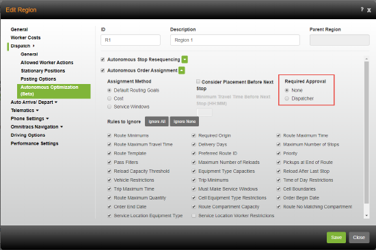
To require approval for autonomous optimization suggestions in a region, you must define who is required to approve the change, the driver or the dispatcher. Add or edit a region and click on the Dispatch tab and then Autonomous Optimization. If the Required Approval option does not display, click the arrow beside the Autonomous Optimization Resequencing and/or the Autonomous Optimization Order Assignment setting.
Choose if you would like to require that all stop resequencing suggestions be approved by the Driver or Dispatcher. You can also choose None, if you prefer the suggestion be automatically accepted.
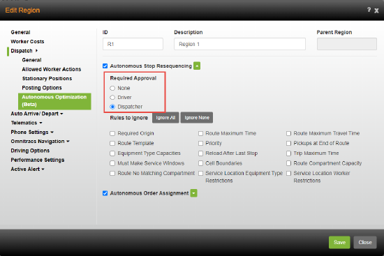
Choose if you would like to require that all order assignments be approved by the Dispatcher or, if you prefer the suggestion be automatically accepted, choose None.
Managing Autonomous Optimization Suggestions
When you enable Autonomous Optimization for a region, if you turn on Required Approval the dispatcher or the driver may need to manage pending suggestions.
Pending Optimizations in Fleetview
In Fleetview, you can identify which routes have Autonomous Optimization applied to them. If it is enabled, an Autonomous Dispatch icon displays in the card and map view and information is included in the autonomous dispatch columns in grid view. If your region settings require that optimizations be approved by the dispatcher, the icon on the card and map views displays red when a pending suggestion exists for the route. The icon is black if the route is eligible for at least one mode of optimization, but there is no pending suggestion, and gray if the route is not eligible for either mode of optimization.
Note: You can sort your routes in Fleetview according to which routes need attention. Click the sort arrow and choose Autonomous Dispatch Needs Attention. You can then sort the routes from A-Z or Z-A.
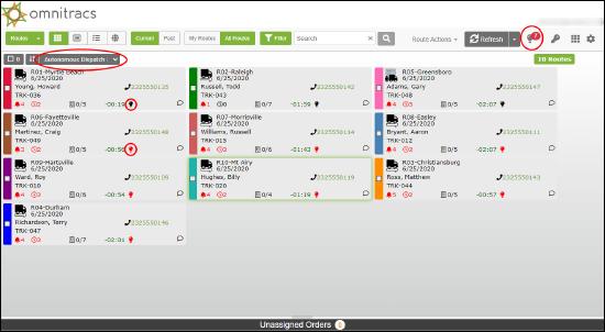
There is also an Autonomous Dispatch icon at the top of the page. When there are routes with suggestions that need attention, a number displays beside the icon. The number represents how many routes have suggestions waiting for the dispatcher's approval. Click the icon to manage the pending suggestions.
The Pending Route Optimization Suggestions window displays with a list of routes with suggestions for optimization. You can view information for previous and new costs, distances, times, and missed time windows for each route by scrolling through the columns. Place a check in the box next to a route that you want to manage and you can also see a summarized comparison of previous and new information in the Details panel of the window. You can see the information for the route as it currently exist, which is the Previous Value, and information on how it will look if the suggestion is approved, the New Value. You also see the Difference between the values.
Note: To see how suggestions affect a group of routes, check the boxes besides the routes you want to manage as a group. The summarized values and differences of the group display in the Details panel.
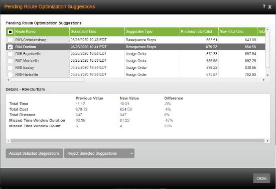
Once you have analyzed the route suggestions, you must accept or reject the changes to a route. Check the box beside a route and click [Accept Selected Suggestions]. If you want to reject the suggestion, click [Reject Selected Suggestions]. If there are existing Route Optimization Rejection Reason Codes available, you are required to select a reason code from the list that displays when you click [Reject Selected Suggestions].
Notes: You can accept or reject multiple routes at the same time. Check the box beside each route you want to manage and then choose to accept or reject those routes.
Route Optimization Rejection Reason Codes are added in Maintenance > Route Optimization Rejection Reason Codes.
If a route suggestion expires before it is accepted or rejected, the red icon indicator no longer displays on the route in Fleetview and the Suggestion Status, seen on the Optimization tab for the route, is assigned a status of Dispatcher No Response.
Click [Close] to close the Pending Route Optimization Suggestions window and return to Fleetview.
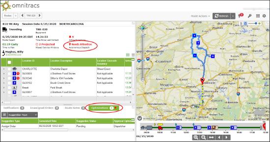
When viewing details for a route when there are pending suggestions, the Autonomous Dispatch icon displays red and reads Needs Attention. The Optimizations tab shows all suggestions for the route and the status of those suggestions. The total number of suggestions for the route displays on the tab and the icon shows red when there are pending suggestions. Click the Optimizations tab to see the type of suggestions that were made, order assignment or resequence of stops, the date and time the suggestions were generated, and the status of the suggestions, Pending, Accepted or Rejected. You will also see information such as who approved or rejected the suggestion, any rejection reason codes, and the date and time it was reviewed.
Pending Optimizations in Roadnet Mobile
If your region settings require that optimizations be approved by the driver, when suggestions are received on the mobile device the driver must accept or reject them. Drivers already have the ability to manage optimized routes on the mobile device.
When the driver receives a notification that the route loaded on the mobile device has been optimized, they can choose to accept or decline the changes. They can also choose to decline all future optimizations for the route.
When a route optimization notification is received, the driver will:
- Press the Optimization Available notification on the mobile device.
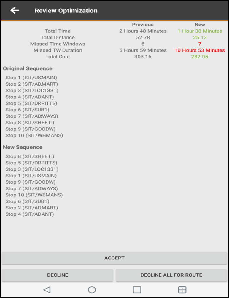
- Review the changes to the route on the Review Optimization screen.
- Press Accept, to accept the changes to the route or press Decline, to decline the changes.
Notes: If the driver declines a suggestion and rejection reason codes exist, the driver must choose a code from the list that displays.
If the driver wants to decline the current changes and all future changes to the route, the driver can press Decline All For Route.
If the driver rejects three suggestions in a row, Omnitracs will stop attempting to optimize the route.
If the driver accepts the suggested changes, the route is changed to reflect the optimization and the dispatcher sees "Driver Accepted" in Fleetview, in the Suggestion Status column on the Optimization tab. If the driver rejects the suggested changes, the status shows as "Driver Rejected". If a route suggestion expires before it is accepted or rejected, the dispatcher will see "Driver No Response" in the Suggestion Status column.
Managing Optimization Settings in Mobile Manager
Previously, you were only able to turn optimizations on or off for routes using the Autonomous Dispatch option under Route Actions in Fleetview. Now, Omnitracs Mobile Manager allows you to turn optimization on and off for individual routes in the mobile application.
To adjust the optimization settings for a route, do the following:
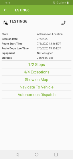
- On the Routes screen, tap the route with which you want to work. The route details screen displays.
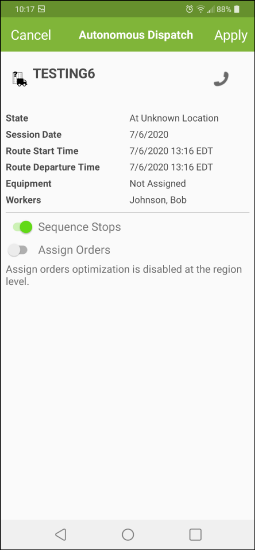
- On the route details screen, tap Autonomous Dispatch.
- Depending on the suggestions you want available for the route, Toggle Sequence Stops and/or Assign Orders on or off.
- Tap Apply.
The Autonomous Dispatch settings are defined for the route. Pending suggestions can be approved by the dispatcher in Fleetview or by the driver on the mobile device, based on the region settings.
Note: Autonomous Optimization must be enabled in Omnitracs before you can manage it for routes in Mobile Manager.
Compliance
More Hours of Service Information Added to Fleetview
Found in Omnitracs Web
To help you stay informed of your workers Hours of Service and Duty Status, more information has been added to Fleetview.
On the Workers grid in Fleetview, in addition to the current worker information, you can now see the following Hours of Service information: if the driver is logged in, the last date and time that the worker logged in and logged out, the ID of the equipment used, the timespan of any consecutive off duty time, and the timespan of any remaining duty time for the week.
Note: The Workers grid can be sorted by the information that has been added.
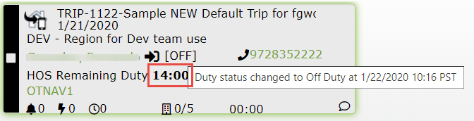
On the Route Cards in Fleetview, in addition to the current route information, a new icon has been added to indicate if a worker is logged in or out. Depending on the status, logged in or logged out, the icon displays black or gray and when you hover over the icon, a tool tip displays a timestamp of the last login or log out.
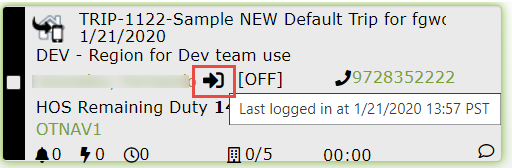
As well, if you hover over the Duty Status information, a tool tip displays indicating the driver's last duty status change.
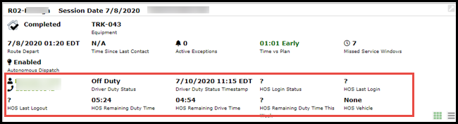
On the Route Details window in Fleetview, the header for a route now includes more hours of service information. You will now see the driver's logged in and out status, timestamp of the last log in or log out, the equipment that is associated with the driver, and the driver's duty time remaining for the week.
Enabling the Canadian 14/180 Fertilizer Hrs Rule
Found in Omnitracs Web
The Canadian Fertilizer Exemption Rule, makes drivers who haul fertilizer in Canada exempt from Canadian cycle reset requirements if they have the appropriate permit. You can now enable the CAN 14/180 Fertilizer Hrs rule for a region and a worker in Omnitracs.
Enabling the rule in a region allows your workers to use the Canadian Fertilizer Exemption rule on the mobile device.
To enable the rule for a region, do the following.
- In the Administration module, click the green button and choose Regions.
- Add a new region or edit an existing region.
- Click HOS Settings and then click Rules and Options.
- Click Select beside the Enable Rules section. A list of available rules displays.
- Check the CAN 14/180 Fertilizer hrs box.
- Click Finished.
- Click Save and then click Close.
Enabling the rule for a worker allows the worker to use the Canadian Fertilizer Exemption rule on the mobile device.
To enable the rule for a worker, do the following.
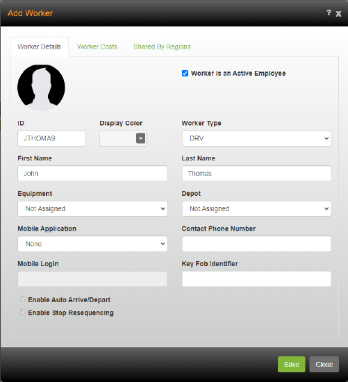
- In the Maintenance module, click the green button and choose Workers.
- Add a new worker or edit an existing one.
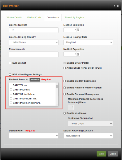
- Click the Compliance tab.
- Click Select beside the Enable Rules section. A list of available rules displays.
Note: The HOS - Use Region Settings box must be unchecked to see the Enable Rules section.
- Check the CAN 14/180 Fertilizer hrs box.
- Click Finished.
- Click Save and then click Close.
Active Alert Web Application
Viewing a Worker's Profile Picture in the Active Alert Web Application
Found in Omnitracs Active Alert Web Application
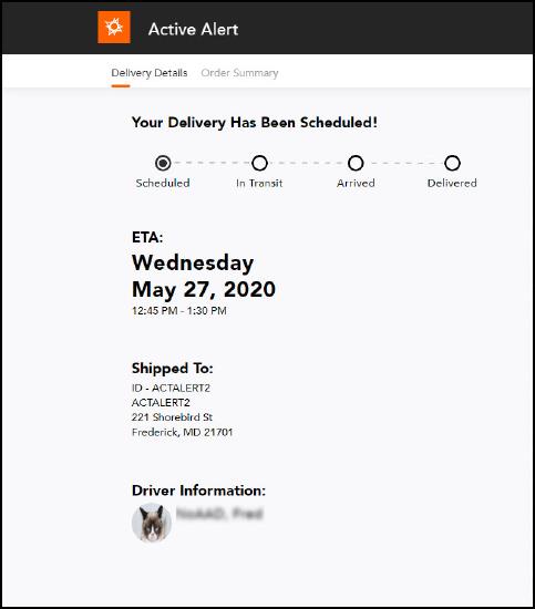
So that your customers are comfortable knowing that the person knocking on their door is an employee of your company, you are now able to add a photo of the worker to the web application as part of the worker information provided with the service status. Providing a driver photo allows your customer to confirm a worker's identity. It can also minimize "no service" visits, when a worried customer refuses service from a person they don't know.
To display a photo of the worker in the Active Alert Web Application, it must be added to the worker's profile in Omnitracs Web. To add the photo, in the Maintenance module, add or edit a worker, click the photo circle, browse to and choose the worker's photo. Then, press Open. The worker's picture replaces the generic image in the photo circle.
Press Save to save your changes.
In the Omnitracs Active Alert Web Application, when worker information is shown on the In Transit, Arrived, Delivered, Cancelled, and Unserviceable screens, your customers will also see the worker's profile picture.
Moving Active Alert Settings from Business Unit to Region
Found in Omnitracs Active Alert Web Application
Currently, Active Alert is set up in the business unit of Omnitracs. This means that you are only able to present one look to your customers, even though you may have many regions with different logos and colors, based on the services that they perform. Now, the Active Alert business unit settings have been moved to the region. You can have a different Active Alert profile for each of your regions in Omnitracs Web.
Note: The Active Alert business unit settings for current Active Alert customers will be automatically moved to the new region pages in Omnitracs Web. Active Alert settings have been removed from Omnitracs Client. You will want to verify that the information that has been moved is correct.
To add or change your Active Alert settings, go to the Administration module, click on the green button and choose Region. Add a new region or edit an existing one. Click Active Alert.
On the Provider page, click the arrow and choose from the list, an email sender and/or an SMS Provider Type.
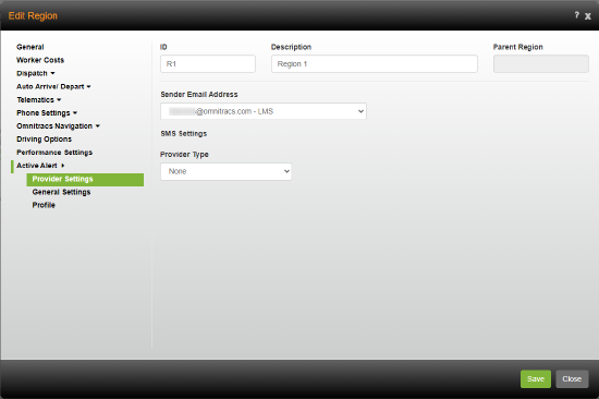
Notes: See the online help for more information about the fields on this page.
For existing Active Alert users, this information has been moved from the previous Business Unit Email Settings and SMS Settings pages. The Email Template Images fields, that were also on the Business Unit Email Settings page were moved to the Email Template Images page in the new Active Alert Profile.
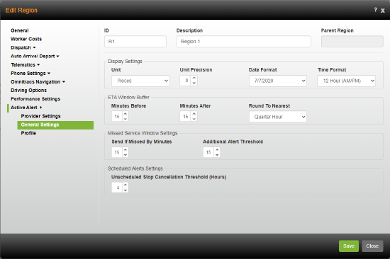
On the General Settings page, choose the options that define how the quantity and date/time information is displayed to your customer, enter the information that will determine how wide the ETA window will be, enter the settings that will be used for sending alerts when it is projected that a driver’s arrival time will miss a service window, and enter the settings that will be used for sending alerts when a stop's route is moved out of Dispatch phase.
Notes: See the online help for more information about the fields on the General Settings page.
For existing Active Alert users, this information has been moved from the previous Business Unit General Settings page.
If you add a new region, Active Alert settings will remain blank until you define them.
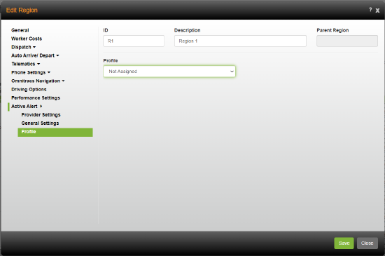
On the Profile page, click the Profile arrow to choose the profile that you want this region to use when displaying the customized web application to your customers.
Notes: See information on setting up profiles in the Customizing Your Active Alert Web Application section of these release notes or in the online help.
For existing Active Alert users, the Profile will default to Not Assigned. When you create a profile, you can return to this page and choose it from the list.
Click [Save] to save your changes.
Configuring Your Active Alert Web Application
Found in Omnitracs Active Alert Web Application
You can now change the look of the Active Alert Web Application that your customer sees when they click on the link in the alert they receive. Each of your regions can have its own theme assigned to Active Alerts. Rather than use the default colors, the text and background can be configured to display in your company colors. You can also add a logo to the top of the page.
To configure the Active Alert Web Application you must create a profile and then assign it to a region.
To create a profile for Active Alert do the following:
- In the Administration module, click the green button and choose Active Alert Profiles from the list.
- On the Web Application page, enter an ID and Description for the profile.
- Click the Truck Location Visibility arrow and choose how you would like your customer to see the truck on the map when they view the web application. Obfuscate shows two blurred circles on the vehicle's position, indicating where the vehicle is located. Not Visible means that the vehicle position does not show at all, while Visible shows the exact position of the vehicle.
Note: When you choose Obfuscate or Visible as the Truck Location Visibility, a tool tip in the web application displays when you hover over the vehicle on the map. It shows how many stops remain until the vehicle reaches the destination. If the destination is the next stop, no message displays.
- If you do not want to configure the web application that your customers see, check the Use Default Theme box and skip to step 9.
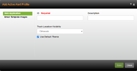
To create a profile that displays a configured web application to your customer, remove the check from the Use Default Theme box. The Customization Settings and Color Setup display. - Enter your Application Title. This appears at the top of the web application.
- Click the Map Type arrow and choose the type of map to display in the web application: grayscale, road, or aerial.
- If you have a logo for your company, you can add it to the top of the web application. To add an image, click [Browse]. Navigate to where the image is stored and highlight it. Click [Open]. The image displays in the Logo Image area.
Note: Image files must be 100kb or less in size.
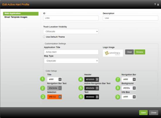
- Define the colors that you want displayed on the alert that your customers see. For each attribute that is configurable, you can enter the HEX color, also known as the hexidecimal color code, that is associated with the color you want displayed in the web application. You can also click the arrow beside the attribute and choose a predefined color.
- Click [Save] to save your new profile. You can create as many profiles as you need.
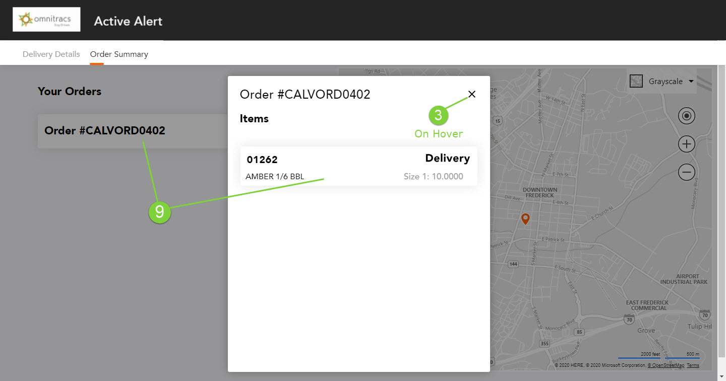
Each configurable attribute is associated with a specific text, selection, or background in the web application. When looking at the Color Setup area of the Web Application page in Active Alert Profiles, the number beside the customizable attribute relates to the same number in the web application below.
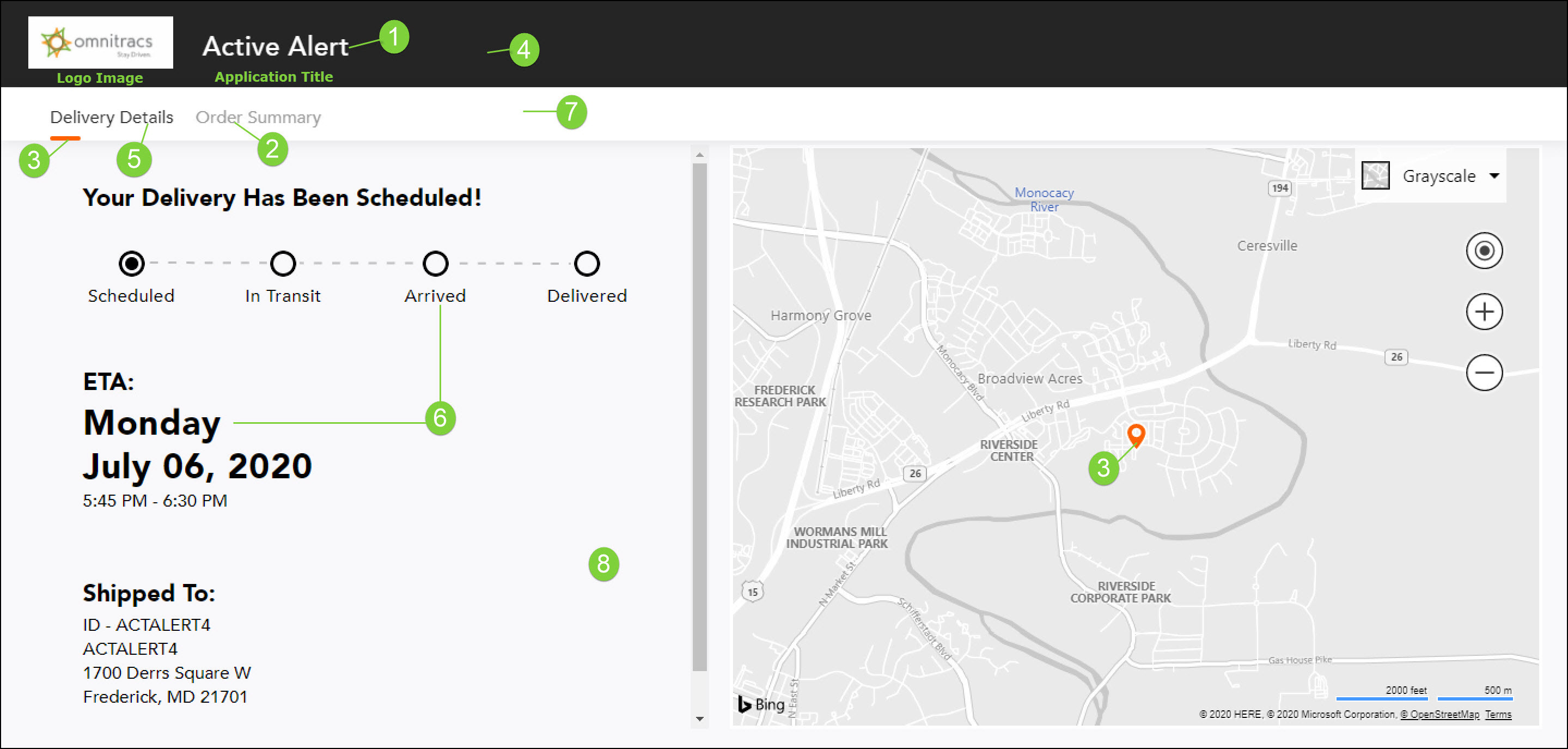
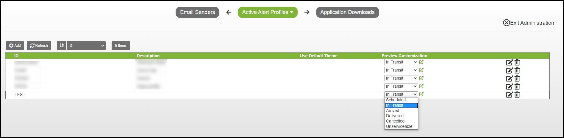
After you save your profile, you can see an example of it in a sample web application.
From the Active Alert Profiles list, for the profile you want to preview, click the Preview Customization arrow and choose the type of page you want to see: In Transit, Scheduled, Delivered, etc. Click the External Link icon and the web application opens, with the customized page displayed. If the page does not reflect what you want, you can return to the profile and make changes. Then, return to the Active Alert Profiles list and preview your web application. You can change it as many times as you need.
Once you have created the profile, before your customers can see your web application with the configured attributes, you must assign it to a region in your company.
- Edit the region to which you want to assign the profile.
- Click Active Alert and then Profile.
- Click the Profile arrow and choose the profile that you want to assign to the region.
- Click [Save] to save your changes.
When your customers view the Active Alert Web Application, they will see your company logo and colors displayed on the page.
Reminder: For your customers to see your configured web application, the <a href="{WEB_LINK}"> Track your delivery </a> tag must be included in the recipient type template, so it is part of the email or SMS alert that is sent to them.
Strategic Planner
Assigning Sequential Route or Territory IDs
Once routes have been created in Strategic Planner, you may want sequential IDs assigned to the routes. This can be very helpful to organize your routes, or to find a particular route in a list. You can enter a Starting Route ID of your choice and Strategic Planner will assign each route a sequential ID. For example, if you have a Washington territory and enter "Washington" for the Starting Route ID, then choose assign, Strategic Planner will assign route IDs of Washington1, Washington2, Washington3, etc.. You can assign sequential routes IDs by right-clicking on a territory(ies), week(s), or routes.
You can also assign sequential IDs to selected territories. Simply select the territories you want included, right click and select Assign Sequential Territory IDs from the menu, and start from step 2 below.
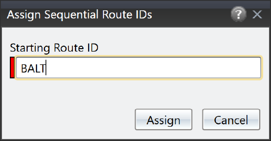
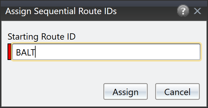
- To assign sequential route IDs to one or more routes, on the Routes list, select the route you want or multiple routes, [Ctrl]+click the routes you want, right-click and select Assign Sequential Route IDs from the menu that pops up, click the [Ctrl]+I, or click the Assign Sequential Route ID icon. The Assign Sequential Route IDs window opens.
Notes: If you want to assign IDs to all the routes in a territory/on a week, right-click on the territory or week and select Assign Sequential Route IDs. All routes on the selected territory(ies)/week(s) will be assigned a route ID.
- Enter the Starting Route/Territory ID.
Notes: If you enter text for the Starting Route ID, Strategic Planner will add a sequential number to the end of the Starting Route ID you enter. For example, if "Washington" as your starting route ID, Strategic Planner will assign "Washington1, Washington2, Washigton3, etc." If you enter a number, Strategic Planner will start with the number you enter and add one for each additional route.
You can enter up to 25 characters and use letters, numbers, and punctuation marks.
- Click the [Assign] button. Strategic Planner will assign each route/territory a sequential ID.
Note: The IDs will be assigned in the order the routes/territories were selected.
Assigning Workers and Equipment to Territories
Found in Omnitracs Client
There may be times when you want to quickly assign workers and equipment to several territories at once, instead of editing each territory individually. Now, using the Assign Workers and Equipment window, you can quickly assign a worker and equipment to a territory and move on to the next one. Additionally, if you assigned buddy equipment to equipment, workers to equipment, or equipment to workers, you can choose to have them automatically assigned to the territory at the same time.
- Select the territory(ies) that you want to assign workers or equipment to.
- Right-click on a territory and select Assign Workers and Equipment. The Assign Workers and Equipment window appears displaying the territories, workers, and equipment. The top of the Assign Workers and Equipment window lists the territories selected to be assigned; the territory currently being assigned is highlighted in the list.
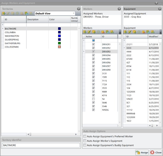
- Select the worker and equipment to assign to the territory.
To assign a worker(s) to the territory, click on the worker in the list. If selecting multiple workers, [Ctrl]+click the workers. You cannot assign more than two workers to a territory. The workers will appear in the Assigned Worker space.
Note: If a worker is not assigned to a territory, the default worker cost for the region will be used.
To assign equipment to the territory, click on the equipment in the list. If selecting multiple pieces of equipment, [Ctrl]+click the equipment. They will appear in the Assigned Equipment space.
To have Strategic Planner automatically assign the equipment's preferred worker, check Auto Assign Equipment's Preferred Worker. The worker is associated with the equipment in the Equipment window.
To have Strategic Planner automatically assign the worker's equipment, check Auto Assign Worker's Equipment. The equipment is associated with the worker in the Worker window.
To have Strategic Planner automatically assign the equipment's buddy equipment, check Auto Assign Equipment's Buddy Equipment. The buddy equipment is associated with the equipment in the Equipment window.
Note: Once an item has been assigned, it is grayed out in the list to indicate that it is already assigned to another territory. - Click the [Assign] button. The information is assigned to the territory. Continue assigning the remaining territories, or click the [Close] button to close the Assign Workers and Equipment window.
- Click [Yes] if you want to close the Assign Workers and Equipment window.
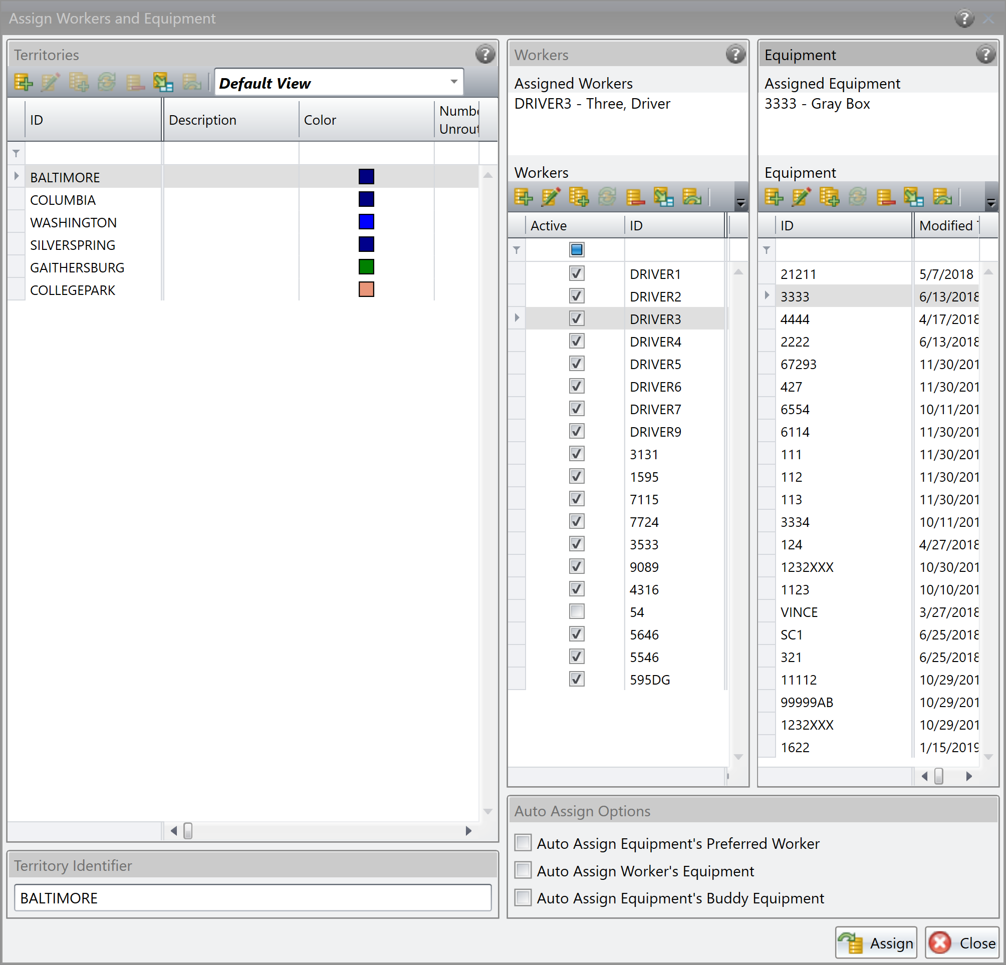
New Service Pattern Set
Service pattern sets determine which weeks and days recurring orders are delivered in Strategic Planner. But, what if instead of a customer receiving their order every Tuesday and Thursday, they want to receive their order every two days? Now, you can create service pattern sets that define the number of days between a customer's delivery, allowing Strategic Planner to more evenly space the deliveries.
A couple of caveats to consider when using Days Between Service:
- The days between deliveries should be evenly divisible by the number of days in the cycle. For instance, a service pattern with 4 days between deliveries would work with a 4 week cycle (28 days) but not with a 3 week cycle (21 days). If the days between deliveries is not evenly divisible, you may get unexpected results, especially near the end of the cycle.
- Each service pattern set can only contain service days between deliveries or weeks between deliveries patterns.
- You can not use anchor weeks or days with Days Between Service service patterns.
- In the region settings, you must check all seven days for the Business Week or routes will not be created.
- If a recurring order has a Days Between Service service pattern set, you will not be able to drag it to the week or day buttons on the map.
- You can only have one service pattern per level when using Days Between Service.
- In the Stops list, the Routed Weeks column will show the current week number, and the Routed Days column will show all days the order is routed in the current week.
- Click on the Planning menu and scroll to Service Pattern Sets. The Service Pattern Sets list opens.
- Click the Add icon; the Service Pattern Set window opens.

- Enter the ID and select Days Between Service as the Service Pattern Type.
- Click the Add icon in the Levels Area.
- Enter the Minimum Quantity and click the Create a new Service Pattern icon.

The Add Service Patterns window opens.

- Enter an ID, Description, and the Days Between Service. Click [Save].
- Repeat Steps 4-6 to add more service patterns to the service pattern set.
- Click [Save] to return to the Service Pattern Set window. Click [Save].
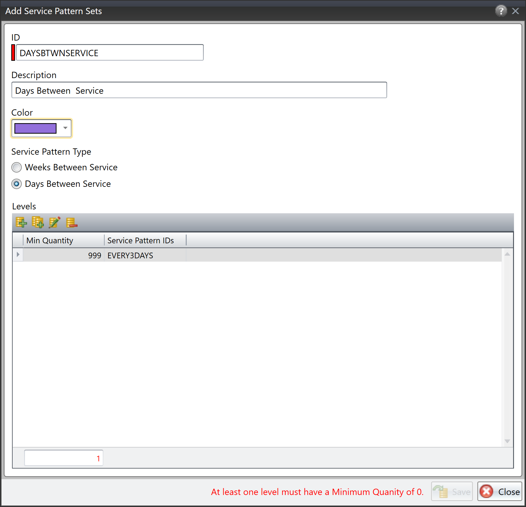
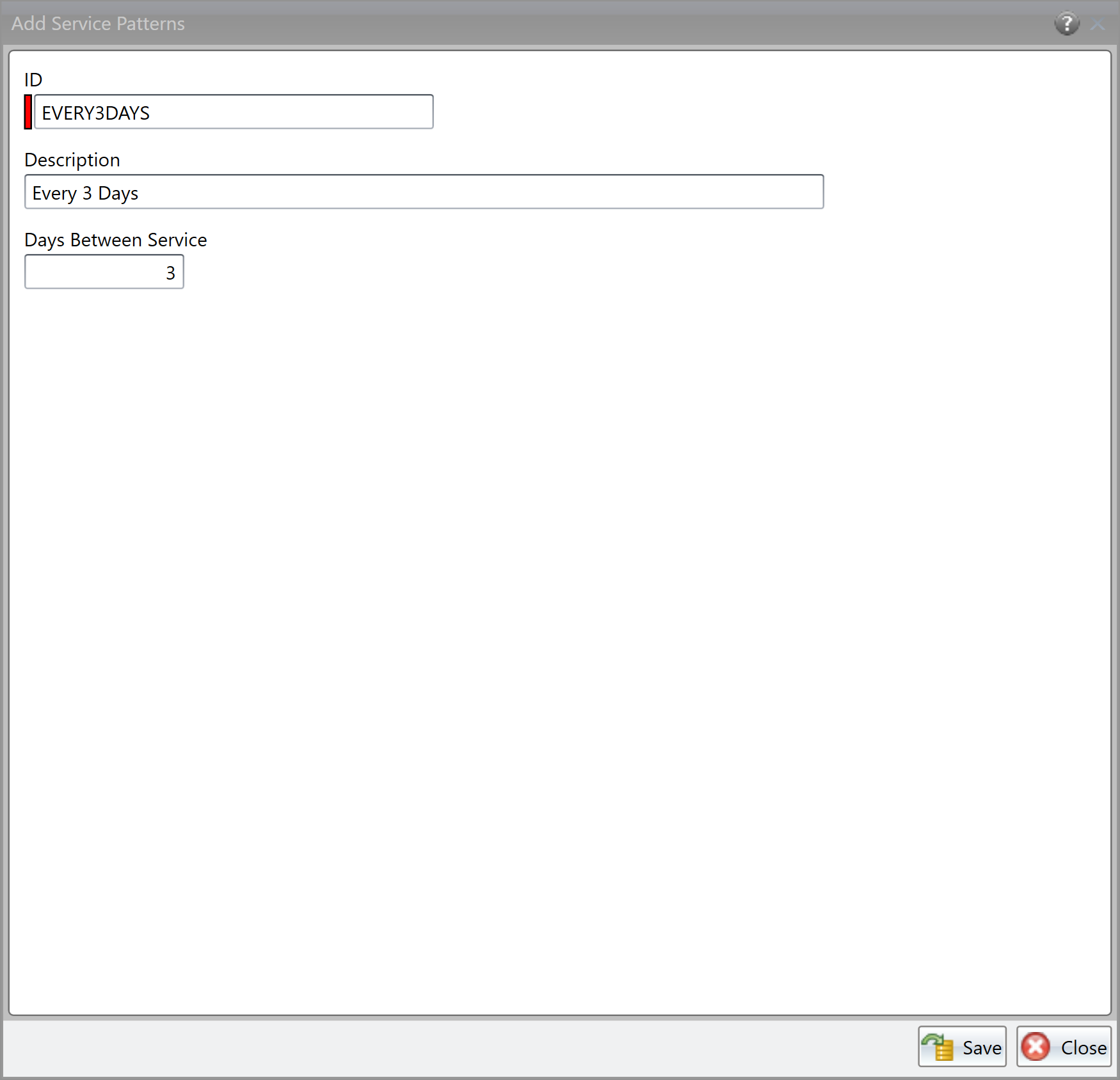
Changes to the Speed Editor
If a recurring order is using a Days Between Service service pattern, you will need to specify the day the pattern should begin.
- Open the Speed Editor.
- If necessary, choose the Service Pattern Set and Service Pattern for the recurring order.
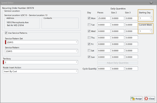
- In the Daily Quantities area, click the Starting Day arrow and choose which day should be the first day of the pattern. The number corresponds to the day of the week: 1= Monday, 2 = Tuesday, 3= Wednesday, etc. Strategic Planner will automatically check the proper days based on the Starting Day and defined days between service for the service pattern.
Notes: When selecting the Starting Day, make sure the Current Week is set to 1.
If you want to see the service days for other weeks, click the Current Week arrow and choose the week; the days for that week will be checked. - If necessary, enter the daily quantity in the first day.
- Click [Assign].
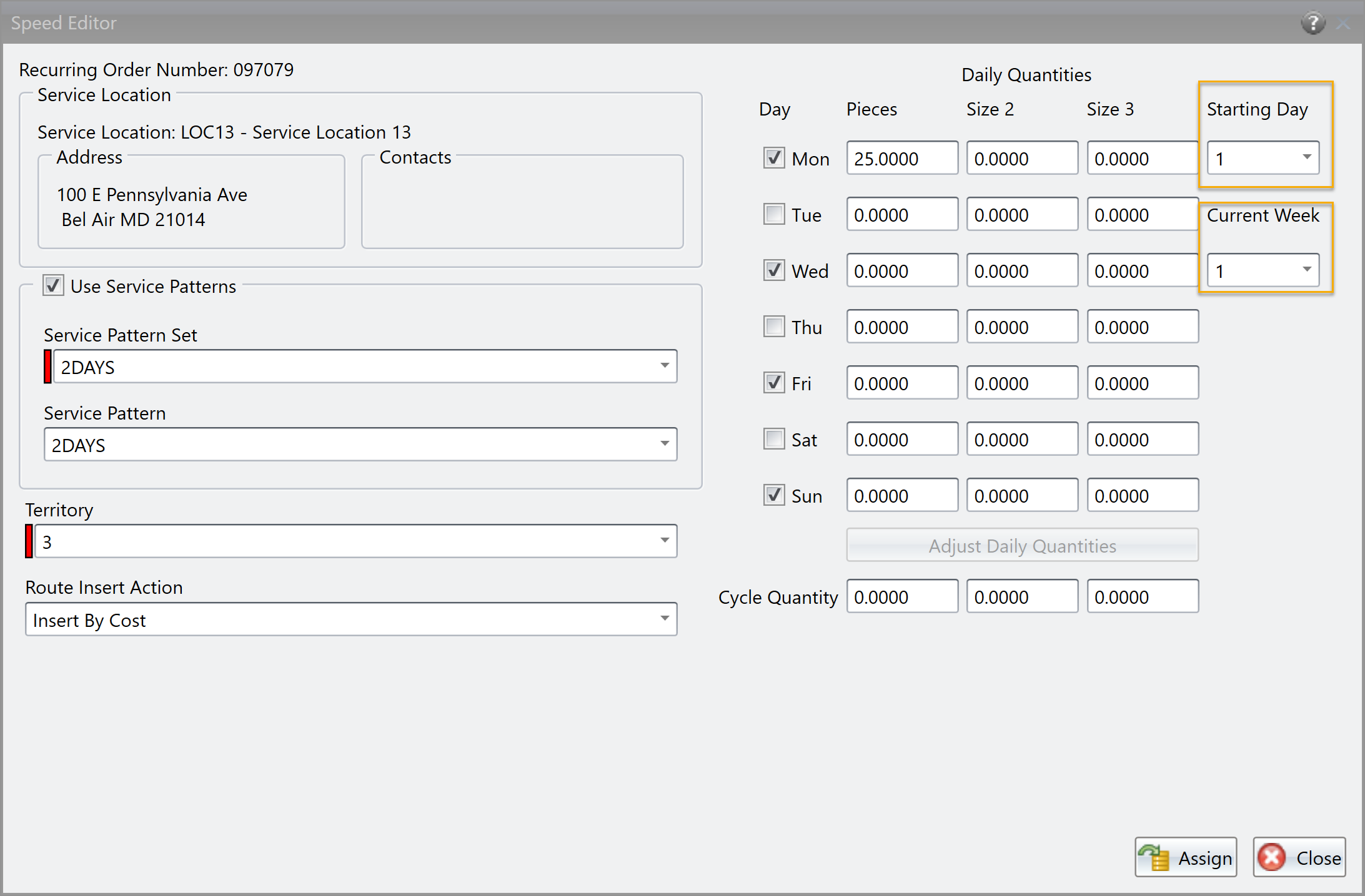
Automatically Creating Reloads
Found in Omnitracs Client
There are times when your truck may not be able to hold all the product to be delivered, so it needs to be reloaded before it can complete the route. Now, when you create strategic routes, you can have reloads automatically added to the routes when needed. You can specify whether the reload is based on the equipment's capacity or how long the route has been run, how long the reload will take, and where the reload should occur.
If you want reloads to be added to the routes, you need to define the options on the Strategic Route Pass Templates - Reloads page.
Note: The maximum number of stops allowed on the entire route, including all trips, is specified on the General page.
- In the Strategic Route Pass Templates window, click the Reloads tab. The Reloads window opens.
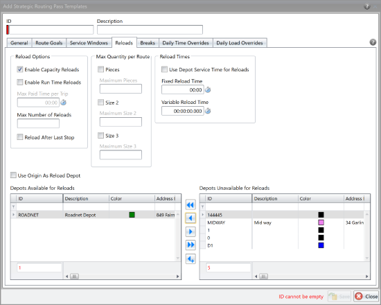
- In the Reload Options section, complete the information that will help determine whether a reload will be created.
Enable Capacity Reloads - check to allow Strategic Planner to reload a truck for another trip based on the truck's capacity. Slide the Capacity Reload Threshold Percent to indicate how full the truck must be to be eligible to be reloaded. The Capacity Reload Threshold Percent is available when the Reload Action is Full or Empty.
Enable Run Time Reloads - check to allow Strategic Planner to reload a truck for another trip based on the route's total run time. All paid time will be included when calculating the run time. In the Max Paid Time per Trip, enter the maximum paid time for the trip as HH:mm. The Max Paid Time per Trip does not include unpaid breaks. For example, if the maximum paid time per trip was 4 hours and the trip was 4.5 hours with an unpaid break of 45 minutes, a reload would not be created because the paid time is only 3 hours 45 minutes.
Max Number of Reloads - enter the maximum number of reloads allowed per route.
Reload After Last Stop - select to automatically have the equipment visit a depot and reload after the last serviceable stop. If the depot (final destination) that the equipment is returning to can reload, then it will use that depot to reload. If not, Strategic Planner will use the origin depot or find the best available depot at which to reload. - In the Max Quantity per Route section, enter the necessary information to limit the total route to a maximum quantity.
Size 1 - Size 3 - check to have the total quantity for the route limited by that size alias. If this option is selected, the total quantity for the route, including all trips, will not exceed this amount. Enter the maximum quantity for that size in the Maximum Size field. - In the Reload Times section, enter the information about how long it will take to reload the equipment.
Use Depot Service Time for Reloads - select if you want to use the depot's fixed and variable service time when reloading. The reload service time is the amount of time needed to reload the truck if it is being sent out for another trip.
Fixed Reload Time - enter the fixed service time needed to reload the truck if it is being sent out for another trip. Enter the exact time using the format HH:MM. If entered, this reload time will be used instead of the depot's service time.
Variable Reload Time - enter the variable service time needed to reload the truck if it is being sent out for another trip. Enter the exact time using the format HH:MM:SS:FFF, where F stands for fractions of a second. If entered, this reload time will be used instead of the depot's service time. - In the Reload Depots section, choose the depots that can be used for reloads.
Use Origin As Reload Depot - check if you want the depot the route started at to be used as the reload depot.
Depots Available for Reloads/Depots Unavailable for Reloads - click the arrows to move depots between the Depots Unavailable for Reloads list to the Depots Available for Reloads list as necessary. Any depots listed in the Depots Available for Reloads area will be considered as reload depots. - Click the [Save] button to save the changes.
- When you are finished, click the [Close] button to close the window.
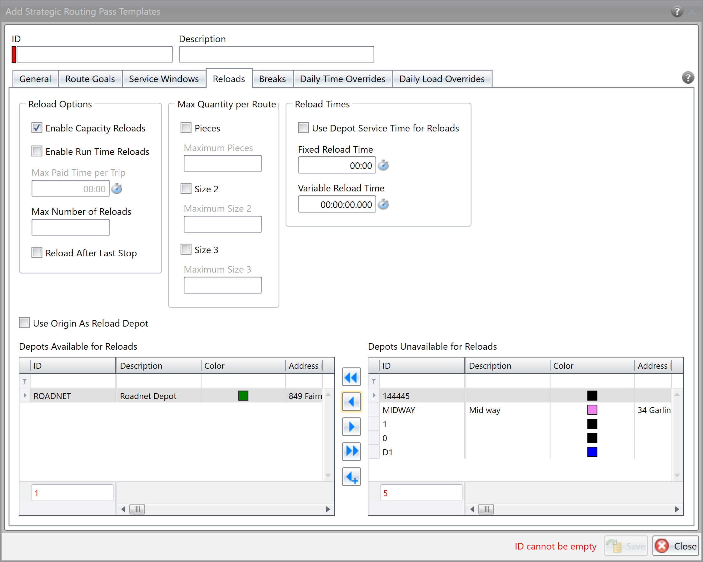
Updates to Export Planning Solution
Once you have created your planning routes, you can export them to your host system so that data can be transferred and used elsewhere in your organization. Several enhancements have been made to Export Planning Solution that allow you to export additional data, as well as control how the data is organized in the export file. The following enhancements have been made:
- You can now specify whether the Day of Week is exported starting on Sunday or Monday. This can be especially important if you run routes for all seven days of the week. In the Day of Week Output area, choose Sunday Based or Monday Based on the Export Planning Solution manifest.
- You can now include any reloads, breaks, or layovers that are on the routes in the export file. To include the reloads, breaks, or layovers, check Include Reloads, Breaks, and Layovers on the Export Planning Solution manifest.
- If you find that it can be difficult to match the data in the file with what it represents, now you can have the field name included as the first row of the export file. To include the field names in the export file, check Include Field Names as First Row on the Export Planning Solution manifest.
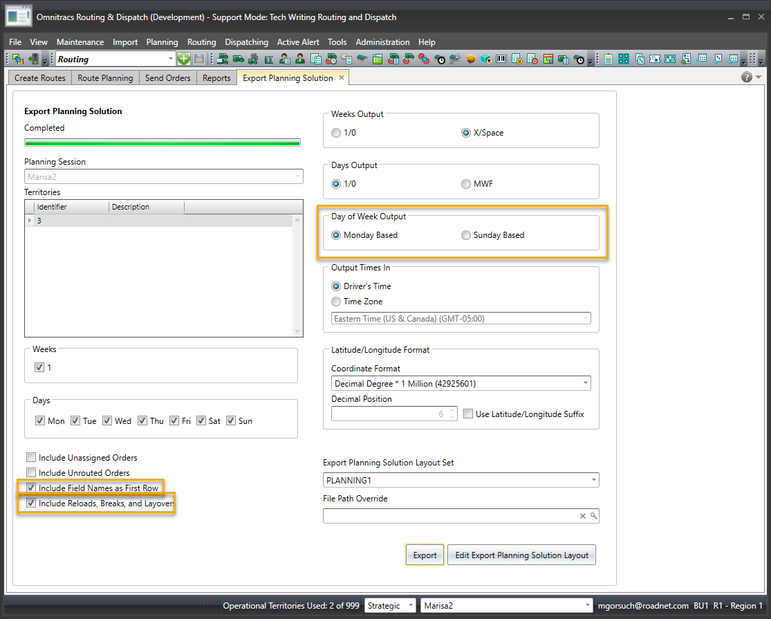
Running the Strategic Planner License Usage Report
Found in Omnitracs Client
A report has been added for Strategic Planner that shows license usage by region. At the top of the report, you will see the Term Start Date, Planning Session Last and Next Archive Dates, and the number of Licensed Operational and Modeling Territories. Information in the report includes the Business Unit, Region, and the number of Operational Planning Sessions and Modeling Planning Sessions for all territories.
There are no options to set for this report. Simply choose the Report Format and click Run.
Insight
Adding Absolute Value to a Custom Measure
Found in Omnitracs Web
An enhancement has been added to Insight's Custom Measures. You can now create a custom measure that uses the absolute value function. When creating a custom measure, in the formula field you can add any combination of abs: all lower case, all upper case ABS, or a mixed case Abs. Insight will automatically convert it to all upper case in the formula line.
Resetting the Columns in a KPI Grid View
Found in Omnitracs Web
If you move your columns around when looking at a KPI in grid view, you will notice that the column order doesn't match up with the KPI when viewed in a graph or the exported .csv file. This is because the grid is simply a view of the KPI and changes to the grid do not modify the actual KPI. As well, the exported .csv shows the order of the actual KPI, not the order of a changed grid.
You can now reset your column order in grid view to reflect the actual KPI. The Reset icon displays when you apply a Grid Visualization to the KPI. When you move a column while in grid view, the Reset icon becomes active. Press the Reset icon to return the columns to their original position so they reflect the actual KPI column order.
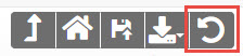
Custom Units for Custom Measures
Found in Omnitracs Web
When you use a custom measure in a KPI, the units on the graph or chart are based on the first measure included in the custom measure's formula. For example, if your formula's first measure displays a quantity, then quantity shows on the graph or chart. If your formula calculates a percentage, you would want percent to show on the graph or chart, instead of quantity.
You can now choose which unit you want to show for your custom measure. The Custom Measure Units list is populated using the measures that are part of the formula. Number, Count, and Percent are always included in the list, as well as the default choice of Auto. Depending on what measures you add to the formula, other units such as Time and Gallons, may display in the list.
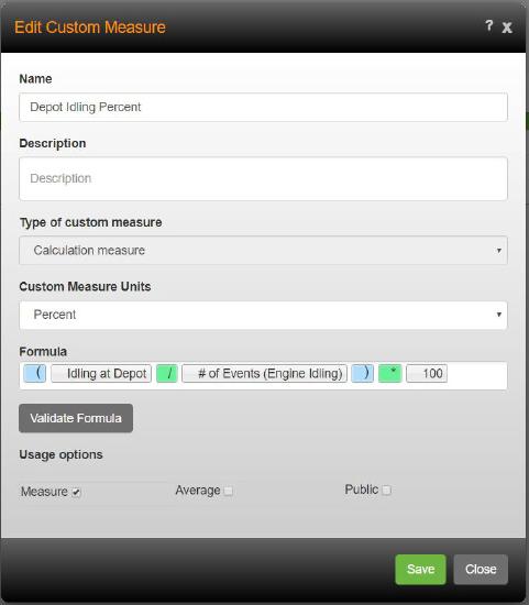
Drive
Sending Trips to Drive/Command Using Fleetview
Found in Omnitracs Drive/Command and Omnitracs Web
Currently, Drive/Command is most frequently used with third party planning applications (e.g. integrated TMS and EPR systems). So that you take advantage of the flexibility of Drive with Omnitracs Routing & Dispatching, two changes have been made that allow Drive/Command to work seamlessly with Omnitracs Routing & Dispatching, a new field on stop types in Drive/Command and assigning workflows to regions and routes in Omnitracs FleetView.
Updating Your Stop Types in Drive/Command
Previously, not all stop types in Drive/Command matched with stop types in Omnitracs FleetView. A new field, Dispatch Stop Types, has been introduced in Command to enable stop types from Drive to post and display real-time information to Omnitracs FleetView. By default, stop types are assigned Generic as the default stop type. If you are currently using Drive/Command, you do not need to make any changes, unless you want to use Omnitracs FleetView for real-time tracking of trips, workers, and equipment. If you are a new Drive/Command user, Dispatch Stop Types are already assigned to stop types in the Drive/Command package. If you are currently using Drive/Command, you will need to assign a Dispatch Stop Type to your existing stop types in Command.
Note: You can find information about Dispatch Stop Types in the online help for Command.
Assigning Workflows in Omnitracs
Drive/Command uses workflows to define how drivers complete their trips. Workflows contain stop types and tasks that guide the driver through their trips. Depending on your business and the types of trips that are run, you may have more than one workflow. A last mile trip may contain a limited number of tasks for each stop, such as arrive, deliver, and depart. While truckload trips might have bump dock and scale tasks included in the workflow. Trips sent from Omnitracs Routing must be assigned a workflow so that as a worker executes their trip, Drive returns stop information for a trip and Omnitracs knows what to do with the information. To aid in this seamless posting of trip data, Drive/Command workflows are now assigned to regions and routes in Omnitracs.
Each region in Omnitracs that sends trips to the Drive application must have a Default Driver Workflow assigned to it.
To assign a Default Driver workflow to a region, do the following.
- In the Administration module, click the green button and choose Regions.
- Add a new region or edit an existing one.
- On the General page, click the Default Driver Workflow arrow and choose the workflow you want to make the default for the region.
Note: Workflows that exist in Drive/Command display in the Default Driver Workflow list.
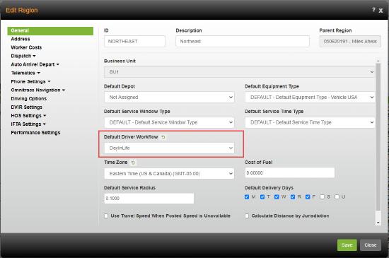
Once a default workflow is assigned to the region that workflow is automatically assigned to each route that is added in Fleetview and Drive. To see this, click Route Actions and then click Add Route. The new field is on the Details tab of the Add Route window.
Note: You can change the Driver Workflow for an individual route. Select the route in FleetView, then select Edit Route. Click the Driver Workflow arrow and choose the workflow you want to assign to the route.
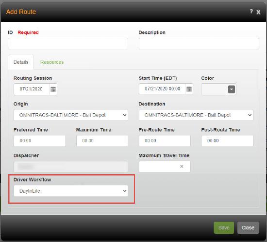
AMG-C
The AMG-C generally serves as a Wi-Fi hotspot for a data tablet/phone running the Omnitracs Drive application. Drive remote communications back to application servers are a Wi-Fi connection from the tablet and then sent to the server over a cellular link using secure internet protocols. When the cellular signal becomes weak, such that data cannot be transmitted, the hotspot is disabled and the tablet will use Bluetooth connection to the AMG-C for critical communications. If a satellite modem is present, the AMG-C will connect to the satellite modem via Wi-Fi and transmit/received a reduced set of transactions.
Satellite Communications
If you have purchased a satellite communication device, the AMG-C can now work with the satellite to send data when a cellular network is not available. However, a reduced set of messages can be transmitted.
Included:
- Driver and dispatch messages to and from Drive including panic messages
- Positions at a reduced frequency is definable but likely 15 minutes to 1 hour.
Not Included:
- ELD messages are not available in satellite mode. While in satellite mode, ELD is in “offline” mode. The driver can maintain his compliance, but the host does not have visibility to his status changes. All of this information is exchanged with the host upon return to cellular coverage
- Other frequent messaging such as fault monitoring, speed information, and frequent positions are all retained in the AMG-C and delivered when the units return to cellular coverage
Link Diagnostic Application Tool
An Omnitracs app called Link is packaged with the AMG-C release to aid in installation and diagnostics of the AMG-C. In this release, there is a function that permits the AMG-C to discover a satellite modem and pair with it for subsequent communications. Pairing is necessary to make sure that an AMG-C on a truck is talking to a satellite modem on that same truck instead of a neighboring truck.
Once the unit is paired, the Link tool can help perform a signal test and return useful diagnostic information so that the installer can determine that the AMG-C and the satellite modem have been installed properly and are working together.
Miscellaneous
Editing Maps to Consider Hazardous Material Classifications
Trucks carrying explosives or other types of hazardous materials are often restricted where they can travel. For instance, often a truck loaded with explosives can not travel through a tunnel. The map data includes the road restrictions for hazardous materials, but you can review the restrictions for a street segment or edit them as necessary.
Note: Hazardous material prohibitions are only available with RouteNet version 12 maps.
- Select the street segment you want to edit.
- Right-click on the segment and choose Edit Attributes. The Edit Street Attributes window opens.
- Click on the Hazardous Material Prohibitions tab. The Hazardous Materials Prohibitions page opens.
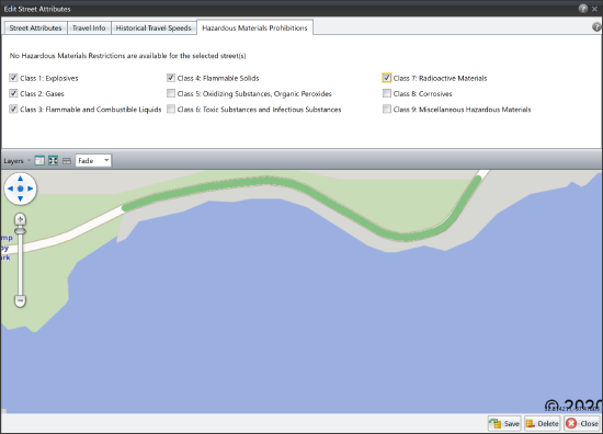
- Check the hazardous material classification that applies to the segment.
- Make any other necessary changes to the segment, then click Save.

Note: As part of this change, the Edit Street Attributes was re-worked. Information that was previously on the Street Attributes page has been split; address information remains on the Street Attributes page, but information dealing with road restrictions, such as whether or not the road is a commercially restricted road, the height and the weight, have been moved to a new Travel Info page.
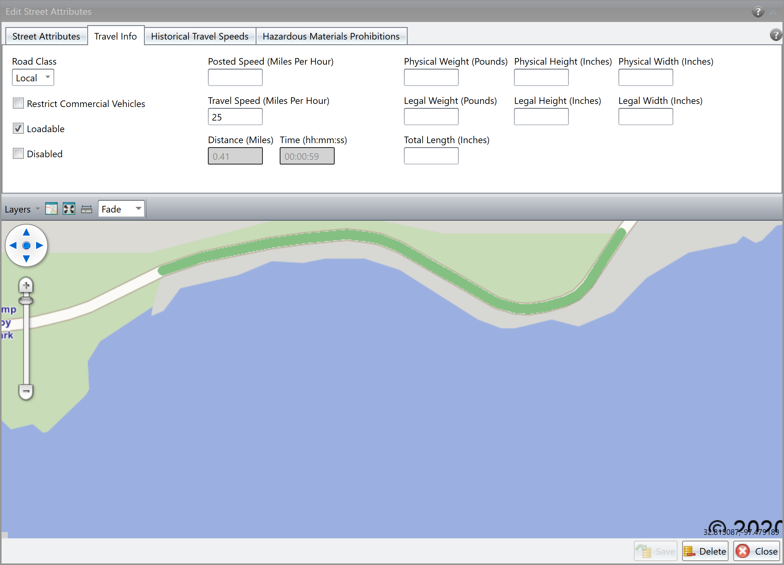
Specifying a Route ID for Unplanned Routes
If you do not use planned routes, your unplanned routes are identified by the equipment's ID and description. However, you may have another way you want to identify the route. Now, you can specify a Generated Route Display Name that will be used to identify the route in FleetView, and elsewhere in Omnitracs One.
To specify the display name for a route, enter the name on the equipment.
In Maintenance, click on the green button and scroll to Equipment. Click Add to add new piece of equipment, or click the Edit icon for equipment you want to change. The Equipment window opens. Enter the display name that should be shown for any route this equipment runs in the Generated Route Display Name box. Click Save.
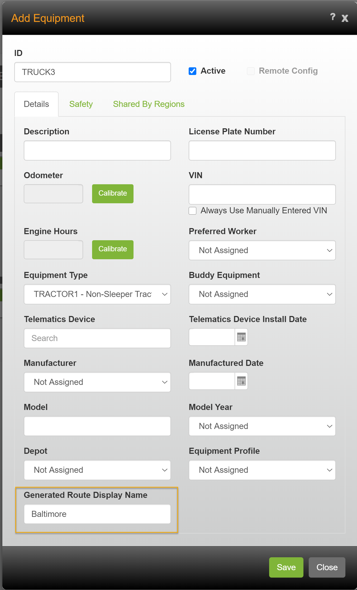
This name will now be used to identify any unplanned route that equipment runs throughout Omnitracs One.
Software Corrections
| Issue key | Release Notes | Components |
|---|---|---|
| RPE-8742 | The Active Alert widget will now display the Text tab when the Feature Set for Active Alert is enabled. | Active Alert |
| RPE-8740 | The issue is caused by recent changes related to moving AA settings from BU to Region | Active Alert |
| RPE-7987 | The Active Alert Widget now displays the Unit Alias for a region. | Active Alert |
| RPE-7754 | The issues with the Roadnet Active Alert web application notification settings for Email and SMS subscriptions have been resolved. | Active Alert |
| RPE-3984 | An issue with the Active Alert Widget retrieving first data for 2000 customers in the corresponding environment has been resolved. Data is now retrieved only for the customer Id specified. | Active Alert |
| RPE-3896 | Active Alert Widget will now dynamically load customer provided cascading style sheet file. | Active Alert |
| RPE-10152 | There was an issue that caused an error when adding a phone number for an Active Alert text. This has been corrected. | Active Alert |
| RPE-10198 | Active Alert Types are no longer unchecked after subsequent imports. | Active Alert |
| RPE-7424 | The Autonomous Dispatch settings at the region level now provide the ability to specify which algorithm rules to ignore when configuring stop resequencing. | Admin |
| RPE-4625 | There was an issue where customers having a large number of depots could see portions of the Administration module to hang when loading. This has been corrected. | Admin |
| RPE-8221 | Mailing List window now scrolls when necessary | Centralized Messaging |
| RPE-8137 | Stop Types updated in Command are now reflected in Stop Details for the route in FleetView. See attachment for evidence | Command |
| RPE-4576 | The following additional Driver HOS data elements were added to the FleetView Route Cards for customers using Compliance: logged in status, last login/logout time and last duty status change time. | Compliance |
| XRS-177 | When the Diagnostic and Malfunction Detail report was exported as a .csv file, the data did not line up properly, the Date/Time column was duplicated, and when there were page breaks the Organization, Driver, and Vehicle ID were bumped to the row below. This issue has been resolved. | Compliance |
| RPE-9186 | The Session Date property was inadvertently displayed on the Import Planning Solution layout. This has been corrected. | Data Transfer |
| RPE-8480 | Fix hazmat converter to accept only 0-9 on import, and error out if not. | |
| RPE-8283 | There was an issue that was causing the system to hang when importing a planned solution. This has been corrected. | Data Transfer |
| RPE-7612 | The Urgency and Priority Override properties have been removed from the Import Recurring Orders dialog as these properties are only on an order and not a recurring order | Data Transfer |
| RPE-7444 | Mobile Device import platform default is now Android instead of Java | Data Transfer |
| RPE-2137 | A defect was discovered in the process that generates the output file of the Send Orders function which caused numerical values to be formatted incorrectly in languages such as Portuguese. This issue has been resolved. | Data Transfer |
| RPE-8324 | There was an issue with view configurations that were shared to all users in FleetView. This has been corrected. | Dispatching |
| RPE-7866 | Quantities are displayed correctly in the Delivery Detail report for an undeliver/redeliver stop when the Business Unit has "Use Line Items" disabled. | Dispatching |
| RPE-9536 | There was an issue that prevented order information from appearing on the Order window in the web. This has been corrected. | Dispatching |
| RPE-9505 | There was an issue that was causing equipment to appear in the wrong region in FleetView. This has been corrected, and the equipment now appears in the proper region. | Dispatching |
| RPE-10199 | There was an issue where it appeared that the driver was taking a break at the wrong location in FleetView. This has been corrected, and now if there is no GPS for the break, the previous stop's coordinate will be used. | Dispatching |
| RPE-8506 | There was an issue preventing planned routes from third party software from being shown in FleetView. This has been corrected. | Dispatching |
| RPE-6188 | The Cease Dispatch action will now complete the route even if unexpected errors occur. | Dispatching |
| RPE-9102 | There was an issue that was causing routes to be automatically completed after 7 days, Now, for customers having routes that last longer than 7 days, there is a setting to increase the Maximum Route Duration for that customer only. | Dispatching |
| RPE-10142 | In some cases, route path deviations were being generated even when the driver did not deviate from the planned path. This has been corrected. | Dispatching |
| RPE-5771 | A defect was found that prevented a user from geocoding a service location directly from the map in FleetView. This has been resolved. | Dispatching |
| RPE-10141 | There was an issue that was causing exceptions to be generated immediately when a custom exception rule was created. This has been corrected. | Dispatching |
| RPE-4512 | Driver direction in Fleetview no longer display each stop's street address twice | Dispatching |
| RPE-4167 | Fixed a bug that caused Cease Dispatch to fail with an unexpected error on unplanned routes with missing event data. | Dispatching |
| RPE-3800 | The Transfer Route Data logic was updated to assign the unplanned route's telematics device to the planned route after the transfer. This was necessary because of a use case where an unplanned and a completed planned route using the same device were transferred. The device was getting unassigned from the planned route with the logic to unassign it from the unplanned route. Then when new data was subsequently received, a new route was created instead of appending the data to the transferred planned route. | Dispatching |
| RPE-3757 | In FleetView - Overview the map marker for in-motion equipment was changed to have a green filled circle when the travel direction is unknown. Previously, when the direction was unknown the marker displayed a green arrow pointing north, which was inaccurate. Additionally, on the hover help for the map marker, the travel direction is not included when the direction is unknown. | Dispatching |
| RPE-7781 | Maintenance locations can now have a duration of up to 99:59. | Maintenance |
| RPE-6199 | Calculated custom properties can now be configured bases on Order Text custom properties. These values can be calculated using the Count, Distinct Count and Concatenate calculation methods. The Sum calculation method is not supported for Order Text custom properties. The calculated values can be rolled up to the Unassigned, Stop and Route grids. | Maintenance |
| RPE-5210 | These devices were added prior to configuring Compliance and they were not synced with XRS. So, they could not be deleted as delete attempt of non-existing XRS entity was failing. Now it is fixed and XRS request to delete such non-existing device is handled properly so such entity can be deleted. | Maintenance |
| RPE-1663 | Batch geocoding is now available for Maintenance Locations | Maintenance |
| RPE-1186 | There was an issue where a service location's delivery days were not being cloned. Delivery days are cloned over to the new cloned service location. | Maintenance |
| RPE-9306 | An issue was discovered where the application can close unexpectedly when performing a Replace action on entities that have text custom properties defined with large maximum length values. This has been resolved. | Miscellaneous |
| RPE-8369 | There was an issue where the wrong help was opening for Import Routed Solution. This has been corrected. | Miscellaneous |
| RPE-4442 | There was an issue migrating a Roadnet Transportation Suite customer when the region already existed in Roadnet Anywhere. This has been corrected. | Miscellaneous |
| RPE-4348 | In some situations, the route query results differed when the user filtered by 'Yesterday' and entering yesterday's date from the calendar picker. This has been corrected. | Miscellaneous |
| RPE-4163 | Category 'Dispatching' was assigned to the help identifier for the Autonomous Dispatch page in Fleetview, under Route Actions. | Miscellaneous |
| RPE-7601 | There was an issue where the Last Order Date being migrated from the Roadnet Transportation Suite was being changed in Roadnet Anywhere. This has been corrected. | Miscellaneous |
| RPE-3758 | There was an issue preventing the proper help from coming up in Mobile Forms. This has been corrected. | Miscellaneous |
| RPE-3277 | Fatal error no longer happens in the Route Query when adding Creation Method as Filter. | Miscellaneous |
| RPE-813 | There was an issue preventing the help for Create Strategic Plan for opening properly. This has been corrected. | Miscellaneous |
| RPE-662 | A help page has been added to the Omnitracs KB for the Manage Processed Routes page in Insight. | Miscellaneous |
| RPE-643 | A defect was found that resulted in incorrectly formatted values for distances and quantities in grid views in the Omnitracs Client for languages other than English. This has been resolved. | Miscellaneous |
| RPE-8511 | Completing a route now unloads without error. | Mobile |
| RPE-8202 | There was an issue that was preventing the driver from loading a route onto the mobile device. This has been corrected. | Mobile |
| RPE-7788 | A Tracking route will now create and arrive at a stop when nearby locations are retrieved and the regional setting for Minimum Stop Time is achieved. | Mobile |
| RPE-5359 | Running "Suggest Route" on an unassigned order in Omnitracs Mobile Manager will only suggest Delivery routes. | Mobile |
| RPE-9700 | Two pane signature view is now displayed fullscreen instead of a modal on iPad. | Mobile |
| RPE-1252 | There was an issue that was preventing a path from being generated under specific circumstances in Navigation. This has been corrected. | Navigation |
| RPE-10387 | There was an issue that could cause the application to skip telling the driver to make a u-turn as the first step in the path. This has been corrected. | Navigation |
| RPE-8252 | There was an issue that was causing the map to open with a blank screen. This has been resolved. | Navigation |
| RPE-9304 | A warning message now appears when the user runs Transfer Session and tries to transfer to a session with a different length (Cycle Weeks) from the source session. If any of the selected destination sessions are a different length the warning appears. | Planning |
| RPE-6181 | Previously, the Route's grid on the Strategic Planning picklist did not populate when routes were dropped on the map. This has been corrected. | Planning |
| RPE-5039 | When dragging a stop or orders to a day or week button on the map for which there are no routes these routes should now be created. Although it still can't violate the pattern and this is only supported for orders with day of week pattern sets that are routed according to a pattern (not manual load distribution). | Planning |
| RPE-3398 | We've resolved a bug which was causing the active session to change when the destination session list on the Transfer Session dialog was double clicked. | Planning |
| RPE-3764 | The 'Update Previous Days or Weeks' feature no longer returns an error when processing a large number of recurring orders. | Planning |
| RPE-4122 | The Create Strategic Routes algorithm now generates Sunday routes. | Planning |
| RPE-5197 | The Export Planning Solution feature now writes all routed days to the output file when the 'Days' field is mapped. | Planning |
| RPE-6019 | An issue whereby the grid windows in the active planning session were blank has been resolved. | Planning |
| RPE-7463 | The 'Update Previous Days and Weeks' function no longer terminates when a selected territory is blank. | Planning |
| RPE-7545 | The application no longer terminates opening a planning session using a custom perspective | Planning |
| RPE-7830 | An issue whereby the routes in the 'Route Days' grid window are duplicated post 'Create Strategic Routes' was resolved. | Planning |
| RPE-7953 | The application no longer terminates when using the Speed Editor and forcing the starting week. | Planning |
| RPE-8007 | The Import Recurring Orders feature now imports Previous Days and Previous Weeks accurately. | Planning |
| RPE-8283 | There was an issue that was causing the system to hang when importing a planned solution. This has been corrected. | Planning |
| RPE-8441 | The application no longer terminates when the Strategic Planning user attempts to change regions. | Planning |
| RPE-8946 | The 'Update Routing & Dispatching' function no longer generates an error when non-serviceable stops on planning routes are added to daily routes. | Planning |
| RPE-7677 | There was an issue where, if a route had multiple pieces of equipment assigned to it, only one piece of equipment was appearing on the csv version of the Distance by Jurisdiction report. Now, if there are multiple pieces of equipment on the route, there is a separate line on the csv version of the report for each piece of equipment, which corrects the problem. | Reporting |
| RPE-6456 | The schedule report form did not preserve saved Mobile Form value - it reset to a very first item in the list. It is corrected. | Reporting |
| RPE-6189 | A new maintenance item type is displayed in the report as "Maintenance Stop" which enlarged one column width and narrowed Order Number column. Appropriate column adjustments were made to fit long order names. | Reporting |
| RPE-10195 | There was an issue where customers with a large number of users would not see all users on some scheduled reports. This has been corrected. | Reporting |
| RPE-5486 | The Route Template Stop List report now includes non-serviceable stops that are on the route templates. | Reporting |
| RPE-5469 | If a report attachment is larger than 5 MB, the following message is sent to the user: "The report for <Report_Description> was too large to attach to an e-mail and will need to be run manually." | Reporting |
| RPE-3989 | The report was displaying the reason code of one order to all the orders on the stop, now moved the reason code to display for each individual order or line item. | Reporting |
| RPE-3863 | In addition to the blank date issue, there was a timezone issue. Modified the formula for Route Date to use the region's default timezone to convert to the local date. |
Reporting |
| RPE-3745 | The report is displaying correct values but the headers Begin and End are misleading so they were renamed to Route Begin Date and Route End Date. | Reporting |
| RPE-3405 | Issue was with routes in multiple jurisdictions. The query ended up creating a copy of the route for each jurisdiction in the route. Now it is corrected. | Reporting |
| RPE-4568 | Fixed an issue so users using iOS in the Mexico region not using a 24 hour clock can log in. | Roadnet Mobile-iOS |
| RPE-5209 | Fixed edit Advanced Geofence for the canceled stops. | Routing |
| RPE-7632 | Previously, certain scenarios would cause Create Routes to fail when compartment routing. This has been resolved. | Routing |
| RPE-5783 | Previously, an error would occur when saving changes to a route template's properties if the assigned Worker, Equipment or Equipment Type was no longer shared the current region. This has been resolved | Routing |
| RPE-4118 | Previously, the Has Stop Alerts flag would display in the route grid even though the stop constraints being violated did not have their respective stop alert flag on the region enabled. This has been corrected. Now, the Has Stop Alerts flag will only display in the route grid when the stop constraints being broken have their respective flag on the region enabled. | Routing |
| RPE-3887 | The Routing Sessions->Can Import permission is now enforced. If a user does not have this permission, new routing sessions will not be created by the order import and the orders will not be imported. An error message pointing the user to the permission is displayed. | Routing |
| RPE-3274 | Made algorithmic enhancements to the route creation and optimization process specifically for transfer orders and orders where not all days of the week are allowed as delivery days. | Routing |
| RPE-10096 | There was an issue that was causing blank custom property fields to be counted when custom properties were being calculated. This has been corrected. | Routing |
| RPE-1170 | When multiple Route Templates were plotted to the map and a new Stop was added to one of the plotted Route Templates, the Stops from the other Route Templates disappeared from the map. This issue has been resolved. | Routing |
| RPE-660 | A defect related to looking up the pre-computed time/distance value of the inserted reload depot resulted in an XY value being returned instead. After moving the reload depot around and returning it to its original position of insertion, the computed time/distance values were correctly used resulting in a difference in total run time. This has been resolved. | Routing |
| RPE-8675 | Integrations would experience an unexpected error when retrieving Events from the REST Event API if a Stop that had Events was later deleted. Added an additional safeguard for Events for which the corresponding Stop no longer exists. | Web Services |
| OIACP-5127 | Power LED indicating BootFailSleep when unit was in VIOP setting. This issue has been resolved. | AMG-C |
| OIACP - 4794 | Expansion kit LED sometimes shows pink after power dip. This issue has been resolved. | AMG-C |
| DCMD-2798 | DVIR now carries over the minor defects from the previous inspection when reopening after SAVE. | Drive |
| DCMD-2572 | The Stop Incomplete dialog is now shown when departing to the next Stop when the current Stop is not completed. | Drive |
| DCMD-2392 | Fixed a display issue where the Photo Capture button was hidden when in portrait mode. | Drive |
| DCMD-2389 | Fixed a sync issue so that new Trips are synced and shown automatically. | Drive |
| DCMD-2384 | There was an issue that was causing the Co-driver login failed message to appear even when the co-driver successfully logged in. This has been corrected. | Drive |
| DCMD-2383 | The Safe to Operate message continued to display after the driver logged out. This has been corrected. | Drive |
| DCMD-2303 | Fixed an issue where the Order ID and any known Trailer Numbers were not shown on the Load Summary dialog. | Drive |
| DCMD-1866 | Removed inappropriate Inspection Points (e.g., Windshield Wipers) from the Canadian Trailer configuration. | Drive |
| DCMD-1330 | There was an issue calculating the Ullage variances. This has been corrected. | Drive |
| DCMD-1329 | There were some issues with work alone time, specifically with the start date/time and date. These have been corrected. | Drive |
| DCMD-1210 | There was an issue where the driver's first truck was still showing as active when the driver attempted to activate a trip in a second truck. This has been resolved. | Drive |
| DCMD-1035 | There was an issue that was causing delivery, pickup, and return tasks to revert to Started status when they were reviewed. This has been corrected. | Drive |
| DCMD-725 | ||
| DCMD-718 | There was an issue causing the pass consigee ID to be sent to the third party system, instead of the pass consignee name. This has been corrected. | Drive |
| DCMD-449 | This issue was resolved by canceling the navigation in progress state and closing the dialog in Drive anytime that the logged in User is logged out of Drive. | Drive |
| DCMD-2798 | DVIR now carries over the minor defects from the previous inspection when reopening after SAVE. | Drive |
| DCMD-2454 | Only the first eight asset types were listed for an inspection in Command. This has been corrected, and you can now scroll to see all the asset types. | Command |
| RPE-8137 | Stop Types updated in Command are now reflected in Stop Details for the route in FleetView. | Command |
| RPE-10305 | There was an issue that was causing engine hours to be reported incorrectly, as well as erroneous GPS pings. This has been corrected. | Telematics |